Programmable Logic Controller Model Train Project
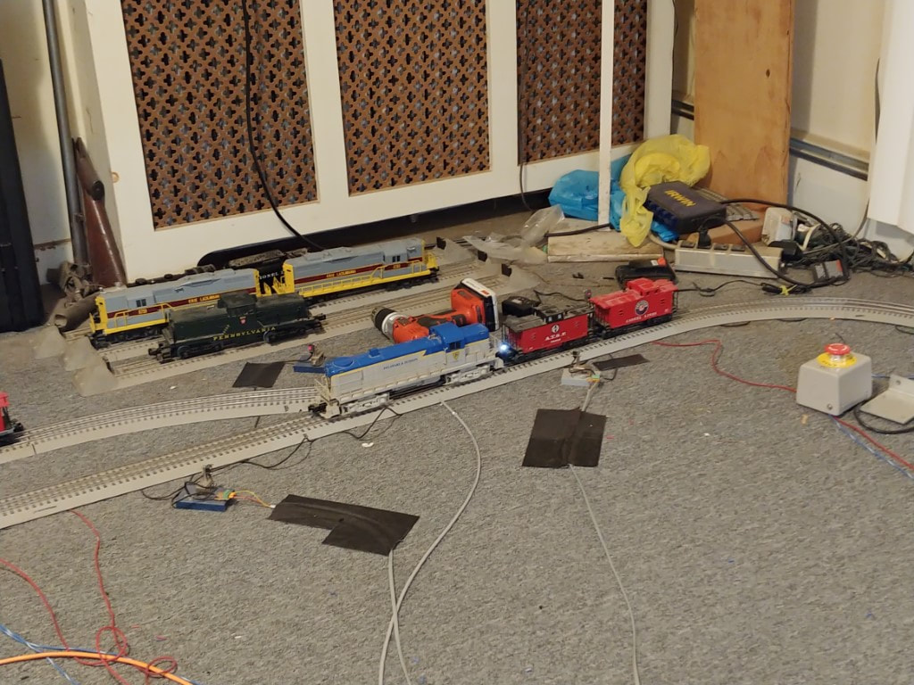
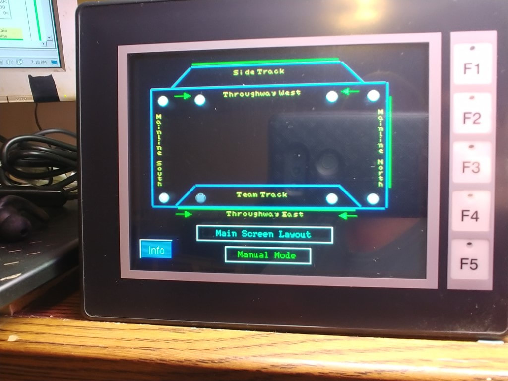
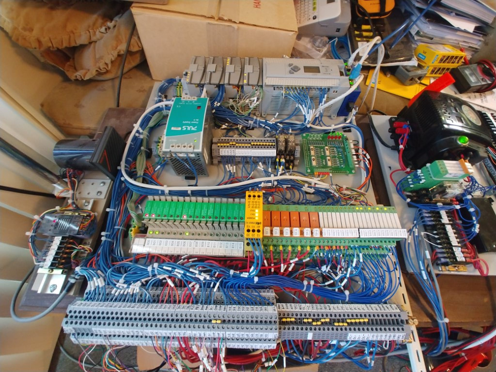
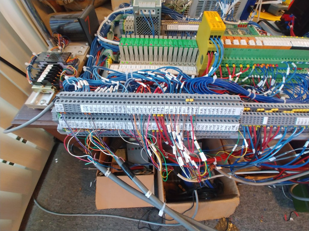
This long term project is to use a programmable logic controller (PLC) to control a model railroad layout. The parts obtained for this project was from former industrial equipment that was being scrapped and I was able to obtain parts from the machines. The project is not practical by normal means as computer and other controls already exist for model trains. The purpose for this project is to learn how to do programming on the PLC. The model railroad layout provides a "real world" example of controls compared to using a training kit which has buttons and switches for input, and simple LED lights for outputs. The electrical design for the project is based around the components obtained from the scrapped machines which is the only practical means to build this project without a high cost for the parts. Eventually the project will be used to control my layout that is around the wall of my room. This will include a HMI panel for control and input.
First Generation Project (Micrologix 1000 PLC)
The first generation of this project was developed with a Micrologix 1000 PLC. This PLC was chosen because at the time units were available second hand and inexpensive. The software to program it is available for free so the initial cost to develop it was kept low. The first generation build involved designing the controls utilizing the components that were obtained from the scrapped machines. I soon ran into limitations with using this PLC unit. One was the I/O is limited and cannot be expanded so several assumptions had to be made with the hardware development. One example is with the remote switches on the layout. The PLC can control the switches, but had no way to verify that the switch did change or did not jam due to lack of inputs. In addition, the memory size of this PLC is limited and by the time I developed the first interchange program, the memory was almost 75% filled. This meant that developing other train operations would be limited. Below is the page with the first generation development of the project which shows how the interface to the layout was developed.
First Generation pictures and videos click here
Second Generation Project (Micrologix 1400 PLC)
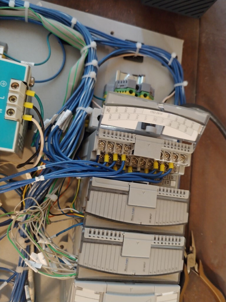
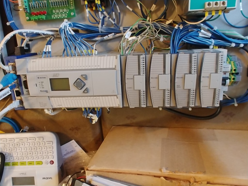
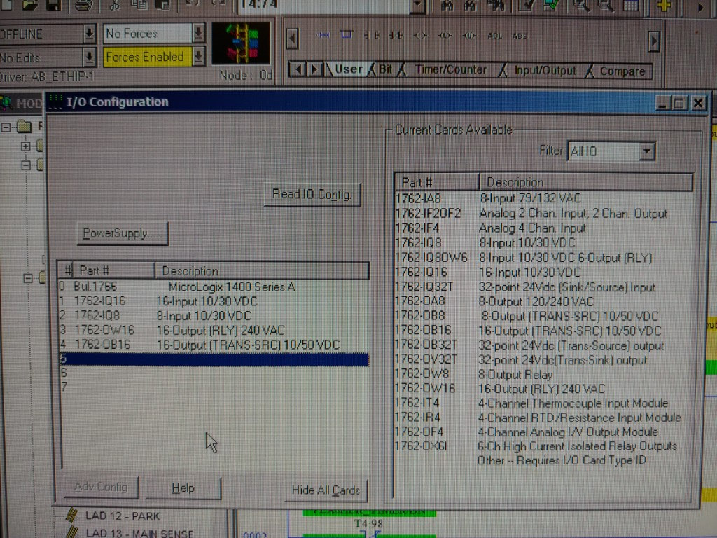
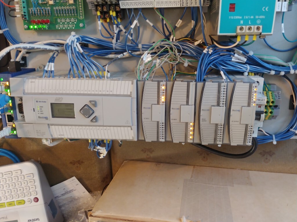
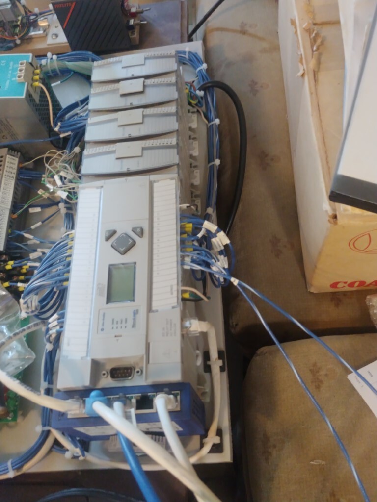
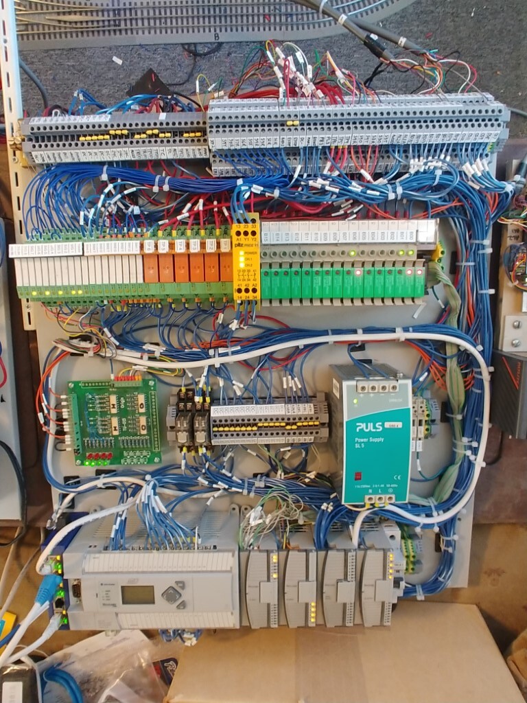
With the above mentioned limitations of the PLC and that now the Micrologix 1000 series of PLC's are now discontinued, I decided to upgrade the PLC. I wanted to stay with an industry standard PLC so I chose to purchase a Micrologix 1400 PLC which not only has more memory for programs, but allows for expansion modules for I/O. This required a complete rebuild of the project from almost scratch to accommodate the new PLC but it also allows for an improved design. This PLC has analog input and output so it will now (hopefully) be possible to control and read the throttle from the Lionel transformer. In addition since this unit allows expanding the I/O with modules, it is now possible, for example, to read the remote switch positions to verify that the switch did not jam.
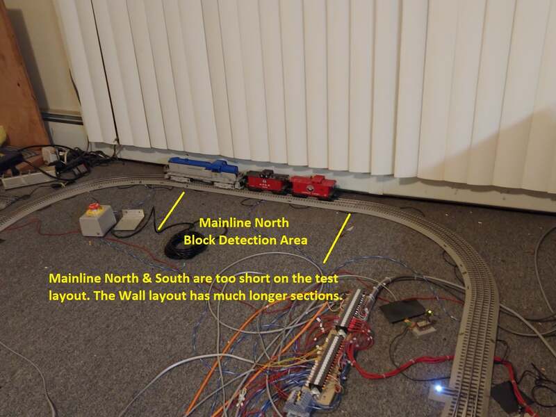
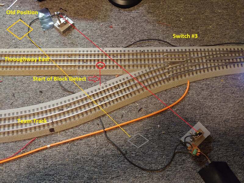
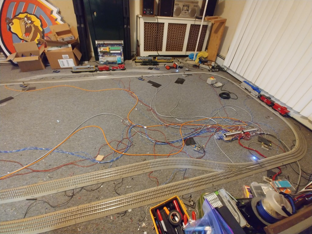
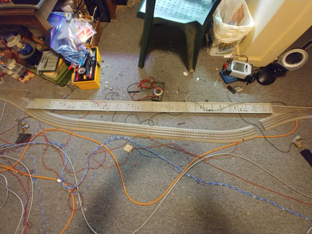
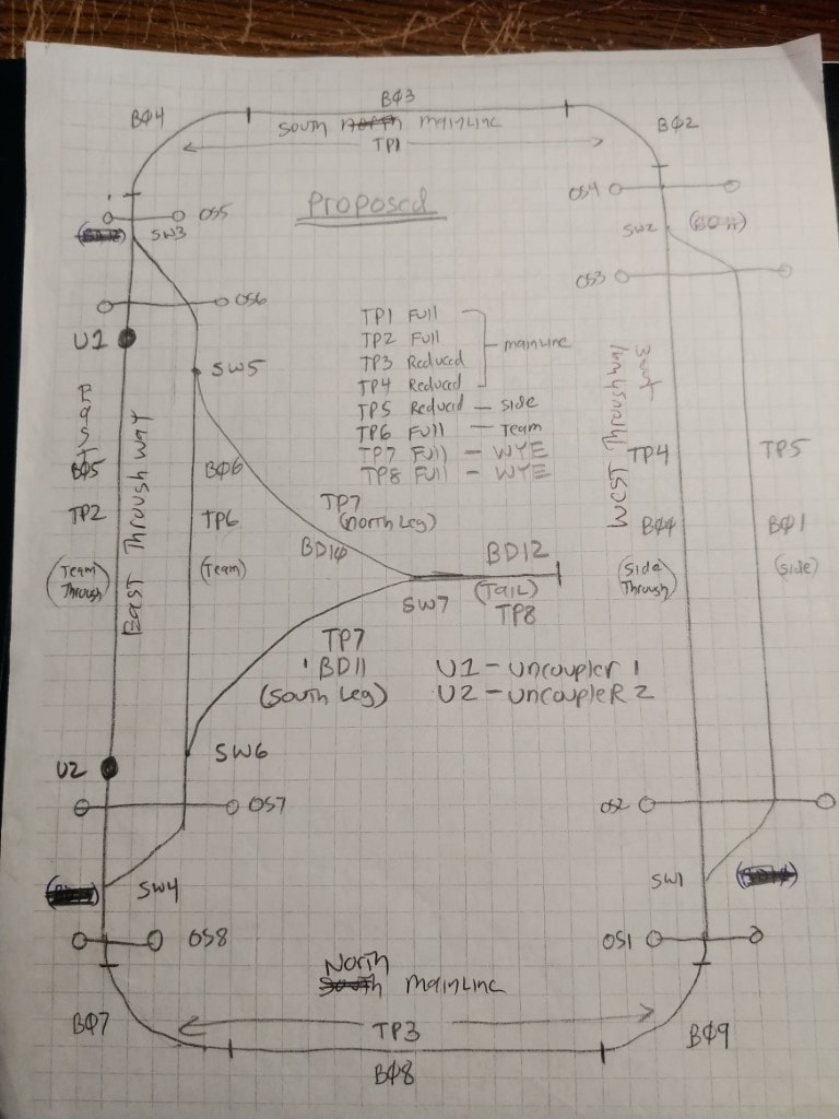
I also changed the layout to have more occupancy block detection on the layout since there is more available inputs with this unit. I also changed the spur track into a team track by adding a fourth remote switch. I also broke up the mainline track power into sections instead of having only one mainline track power control. Construction of this second generation layout can be seen on this page.
Second Generation construction, Click here
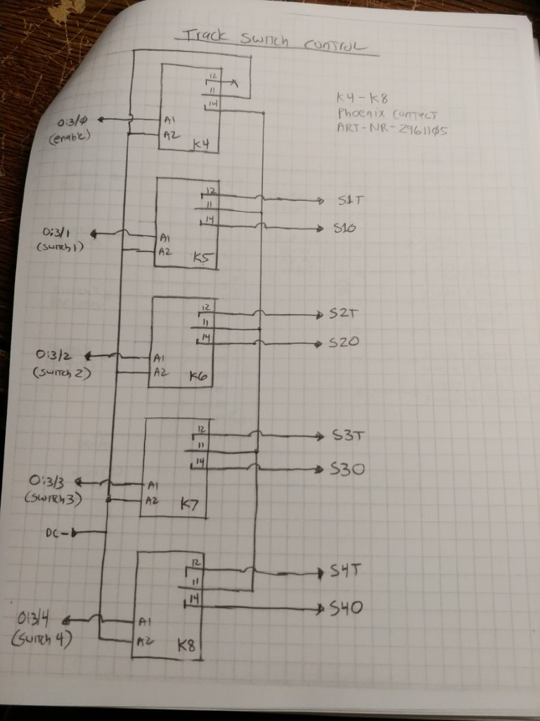
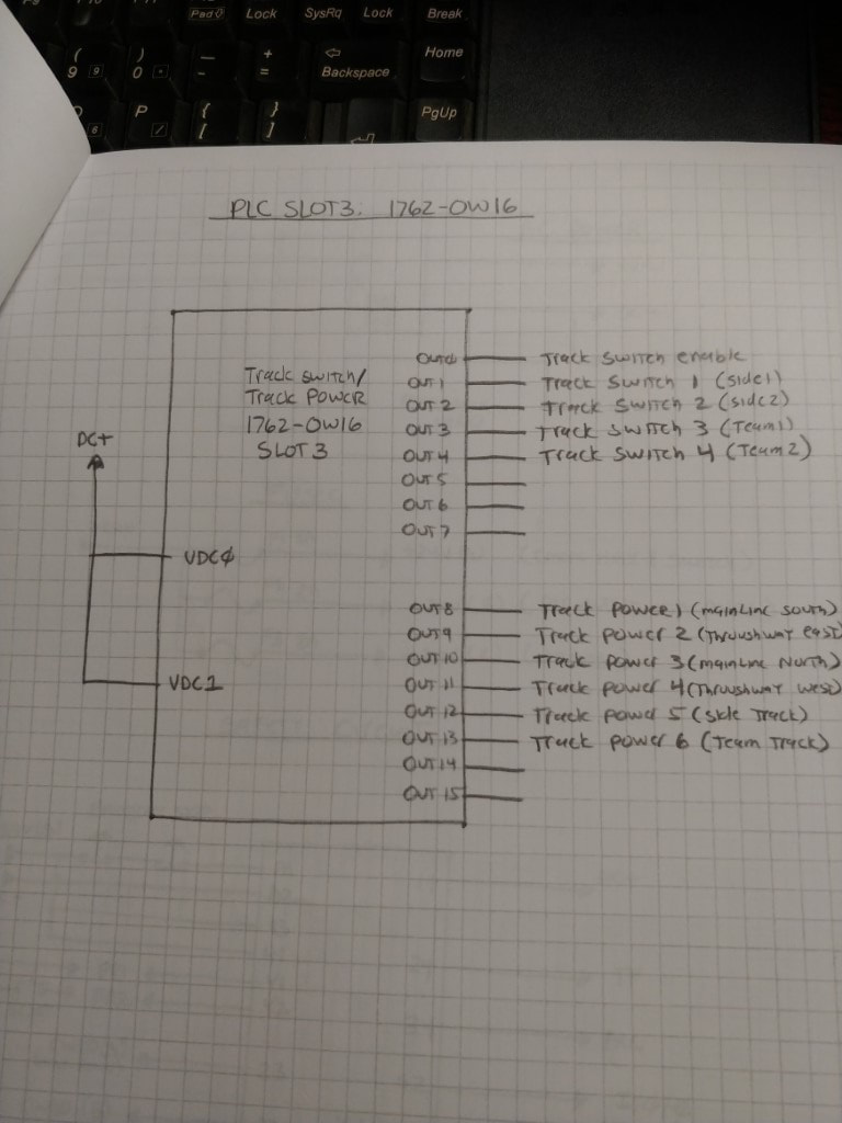
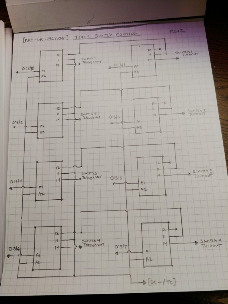
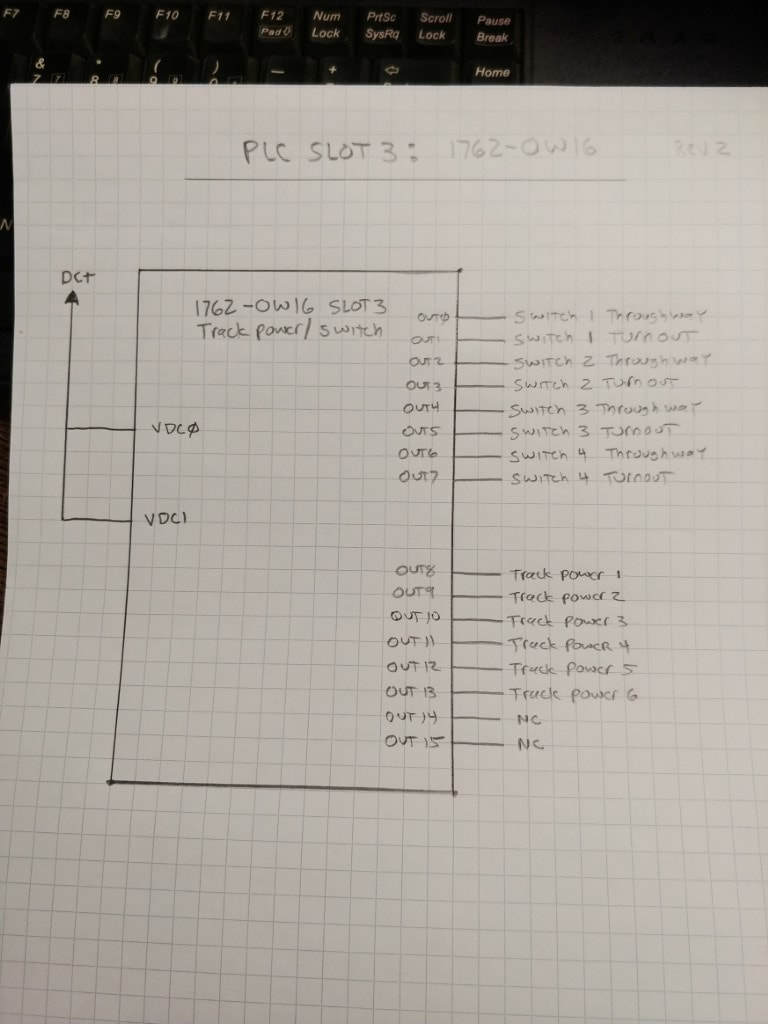
During development of the programs in the first generation project I ran into some issues with the way I was writing the programs. The last working program I wrote was the main and side interchange program. Due to some bad programming practices the next routine I was writing would not work. After consulting with others, I got some good information on better programming practices. The best course of action was a complete re-write of the programs, not only to utilize better programming practices, but to accommodate for the newer PLC and the additional I/O it provides. I decided to build the support routines which will be utilized in the train operations. The link below are illustrations of the second generation controls and the new routines that will be utilized in the train operations.
Second Generation Controls and program routines
Tour of the Second Generation Project Video
CW80 Control Program
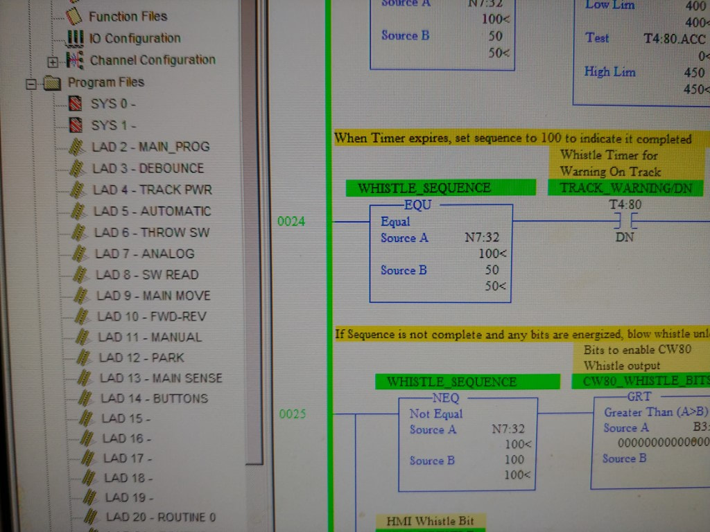
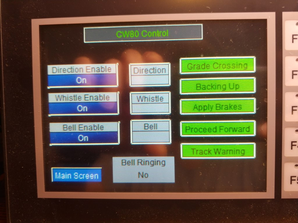
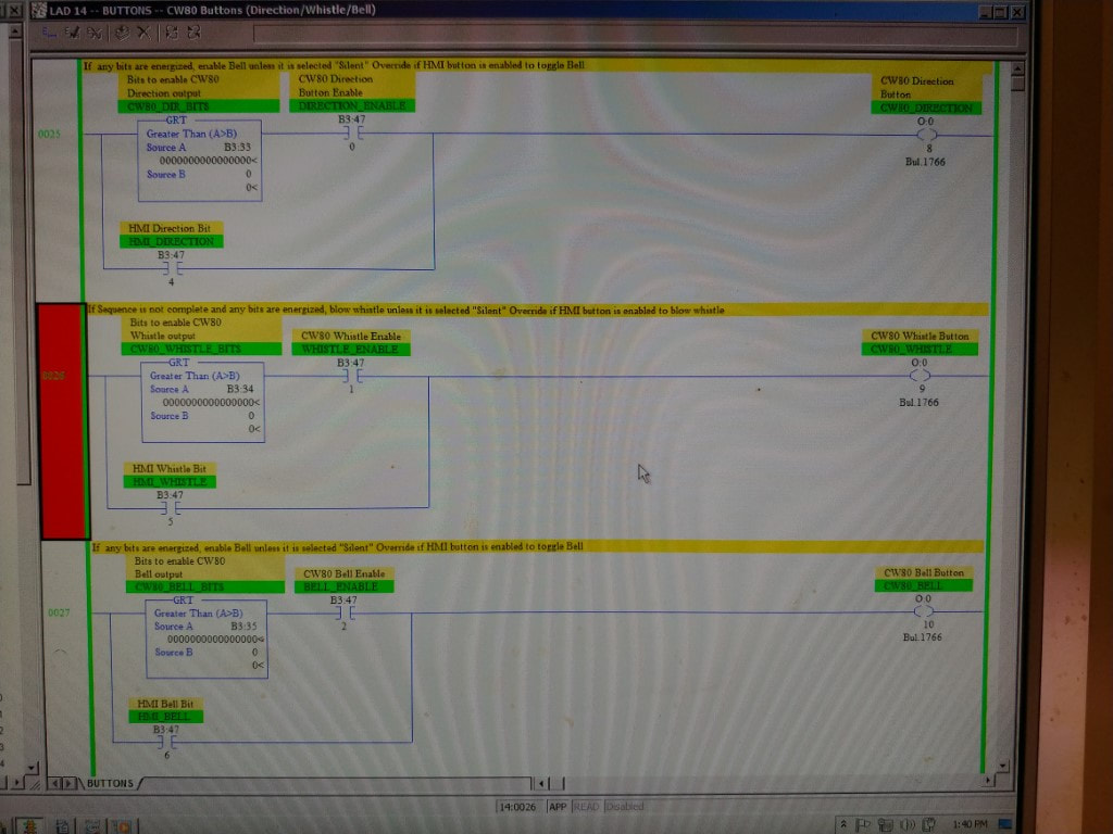
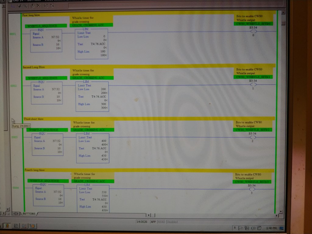
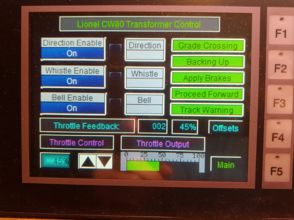
The next routine written is controlling the CW80's Direction / Whistle / Bell button. I moved the ladders for the train operations down to make room for additional support routines. The CW80 HMI Screen was written to allow control of the buttons and to allow disabling them if I want to run the trains without the bell or whistle enabled.
First Routine Development
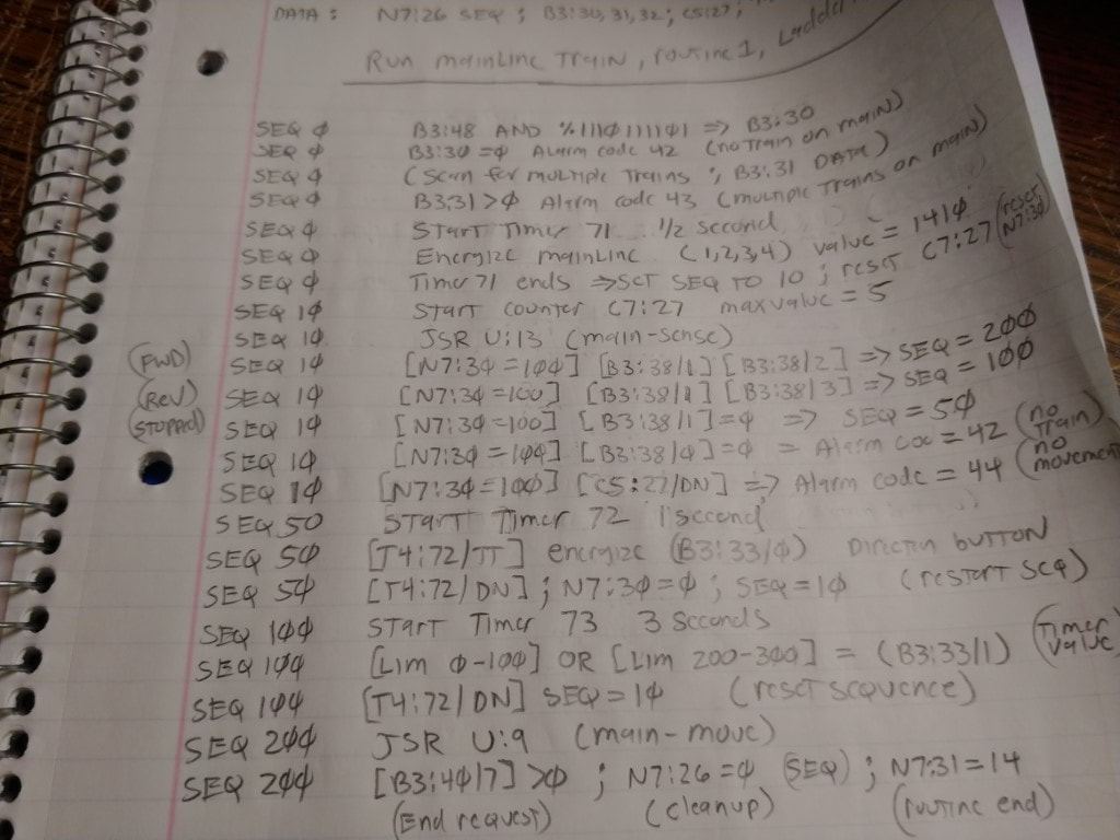
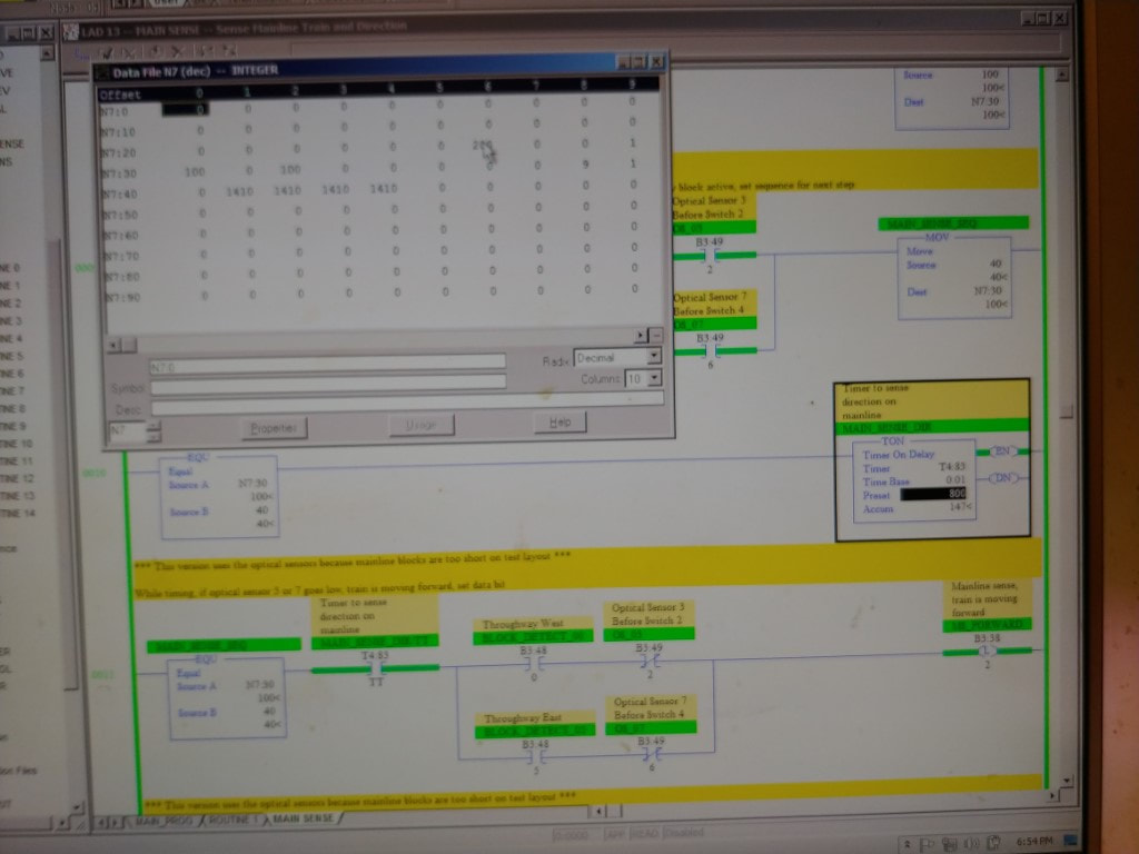
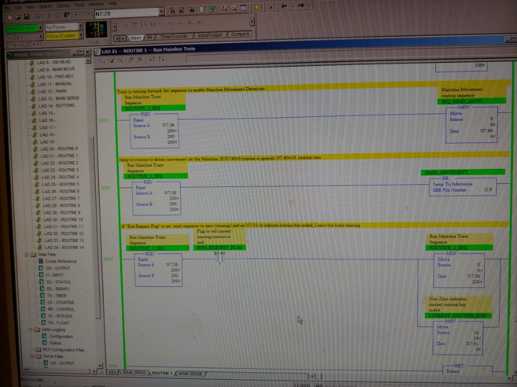
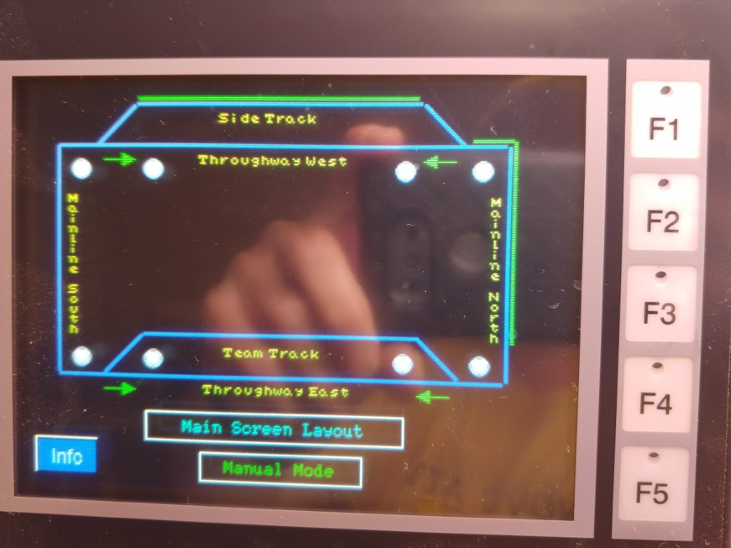
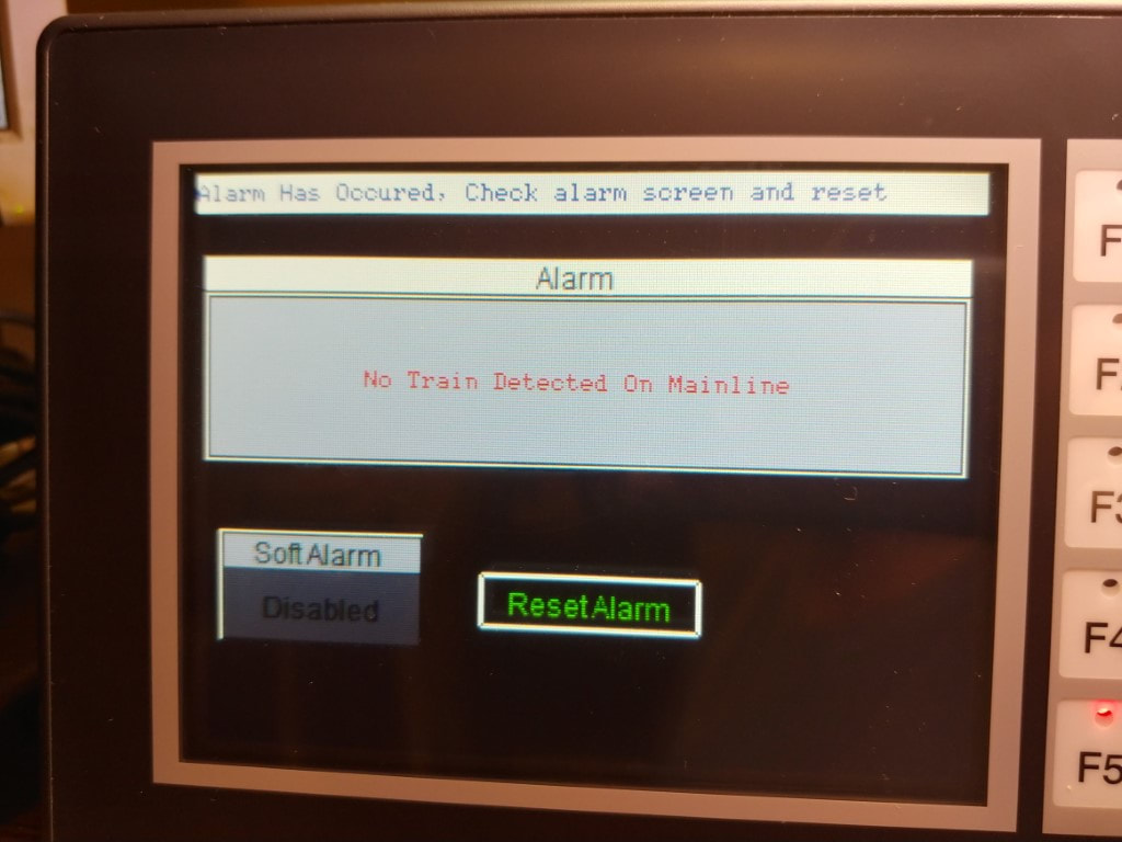
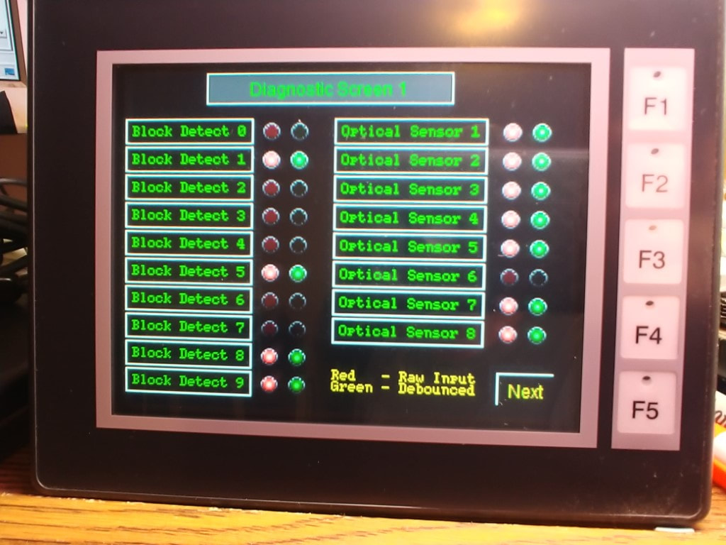
During development of the first routine which is going to run the train on the mainline a few issues came up with the testing of the program. This also shows that the diagnostic screens come in handy when troubleshooting problems with the layout.
Run Mainline Routine
Stop Mainline Train Routine
Main & Side Interchange routine
Main & Side Alternating Run
Demonstration when things don't go as planned.
Locomotive direction control problem
Testing locomotive direction control manually
Proposed fix for direction control problem
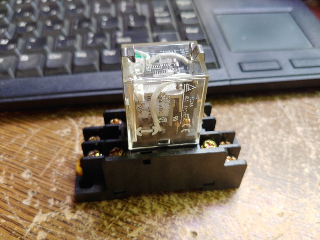
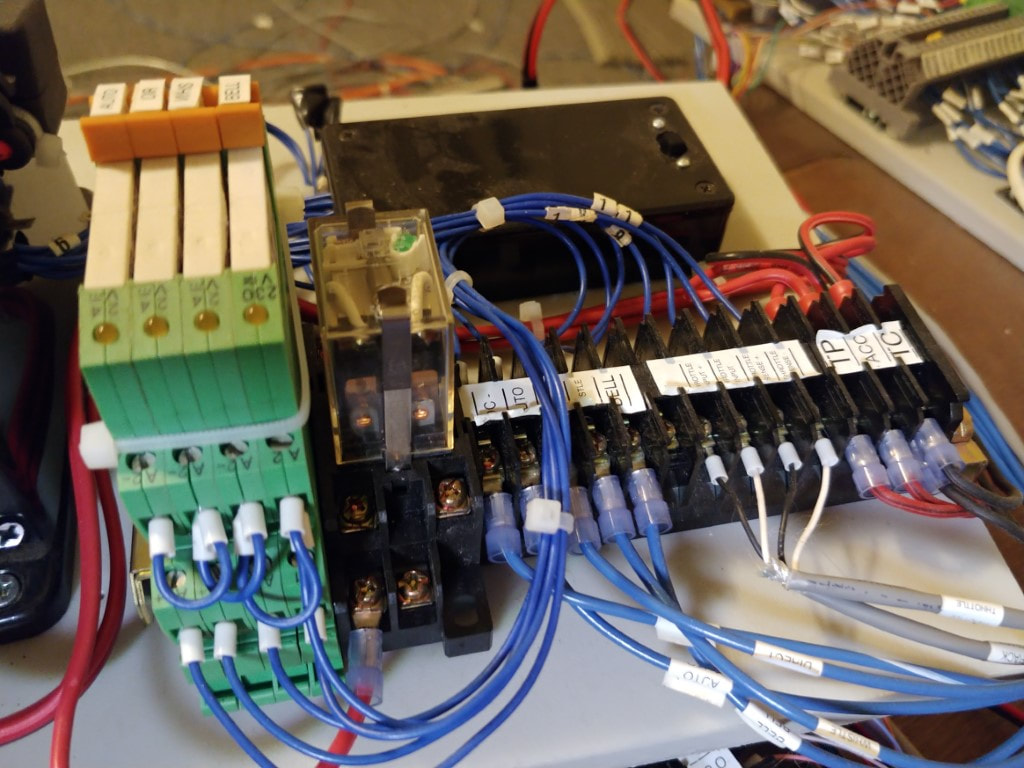
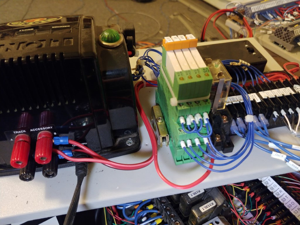
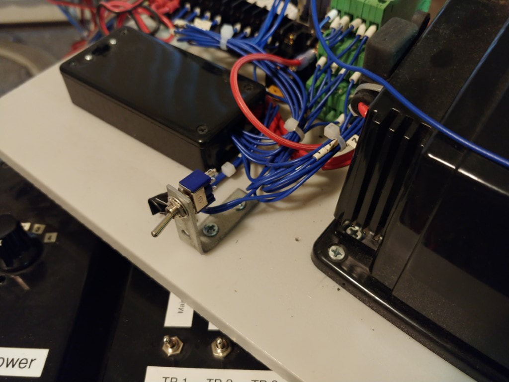
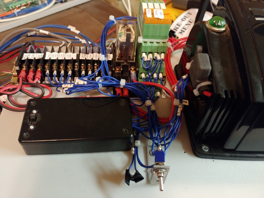
With the direction control of the blue D&H locomotive not working properly. I came up with an idea on how to resolve it. Adding a relay on the CW80 control panel to be used to actually disconnect track power when the direction button is used by the PLC. I added a toggle switch to switch between using the CW80's direction control, or this relay. The results have been mixed. It did help, but the direction control on this train did get worse and I ordered a replacement direction control. I have not installed it yet since as I indicated in the video, this "feature" can be used as a test for the PLC programs to handle situations when things don't go as planned.
Remote Track Switch Problem
Train Operations Demonstration
PLC control of signals
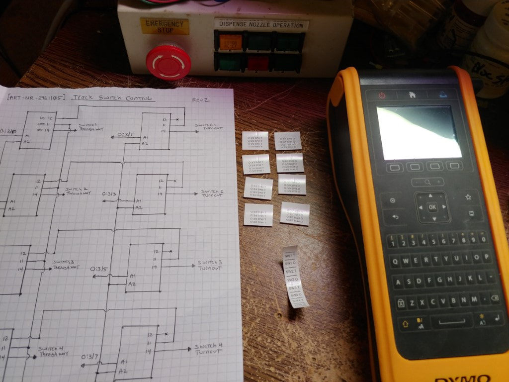
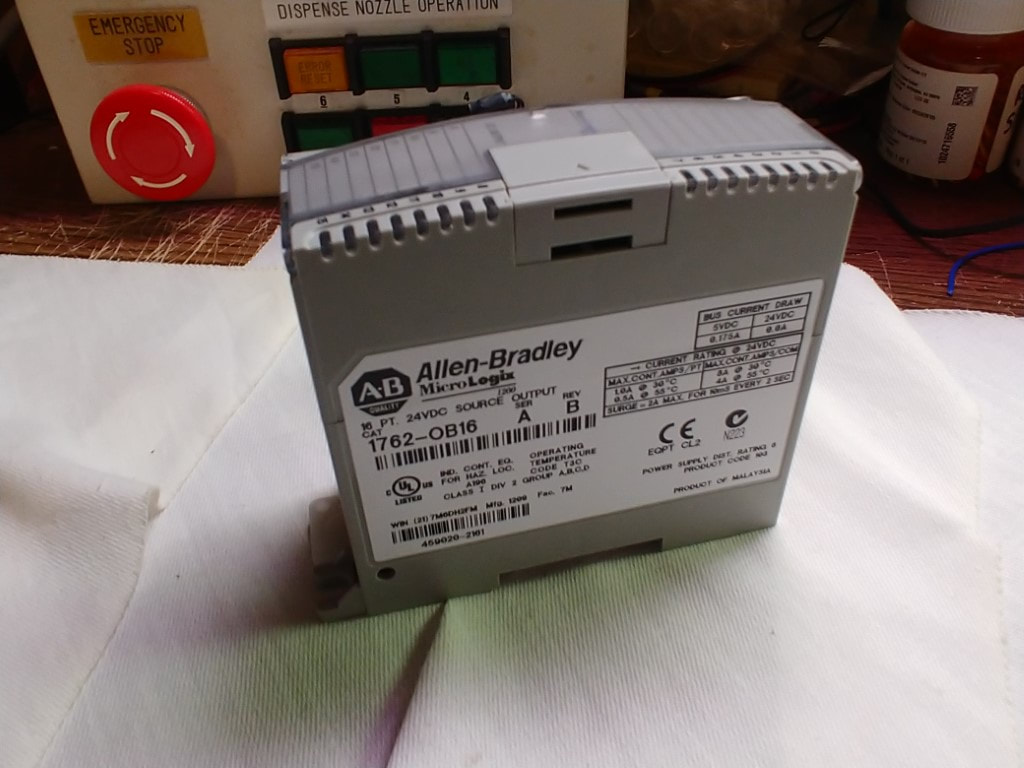
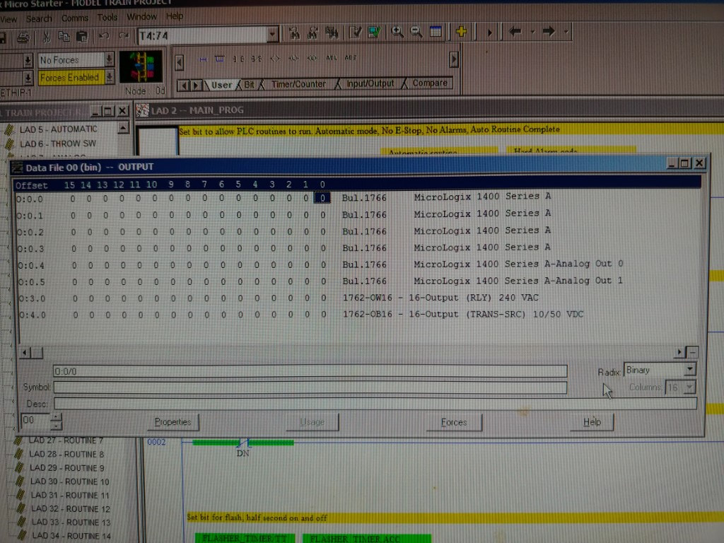
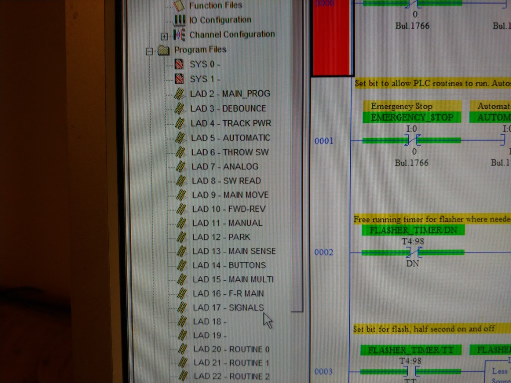
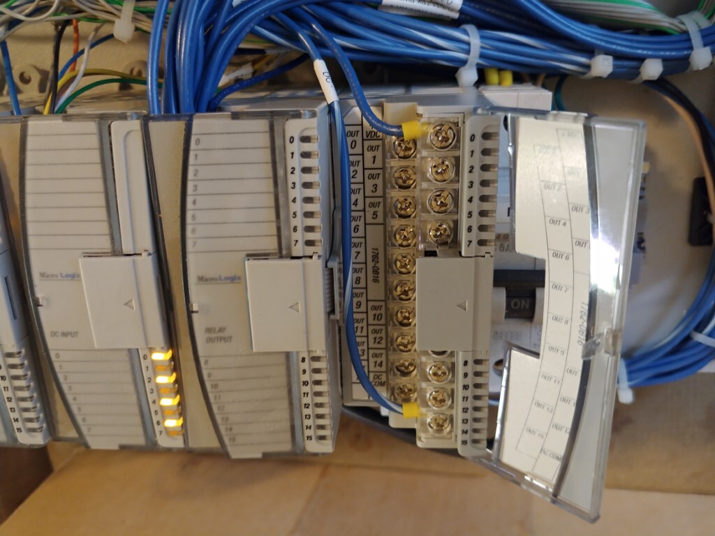
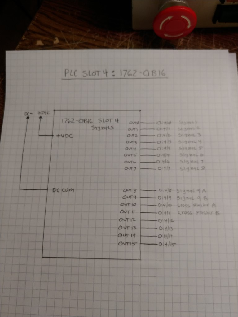
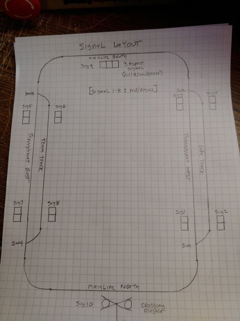
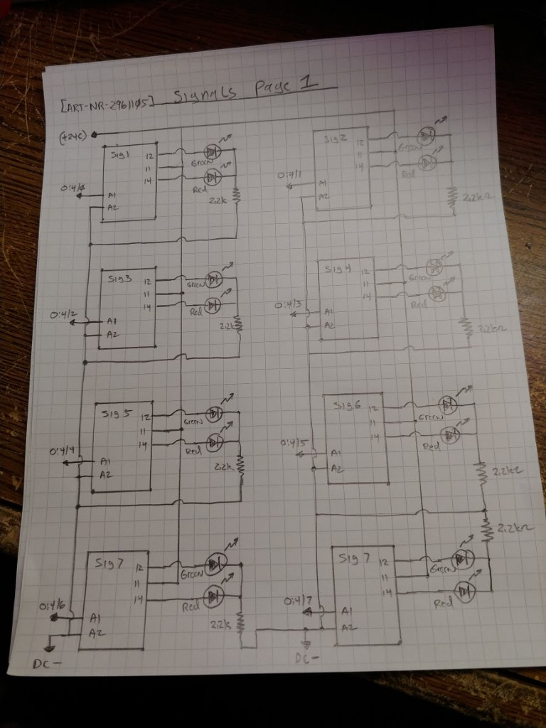
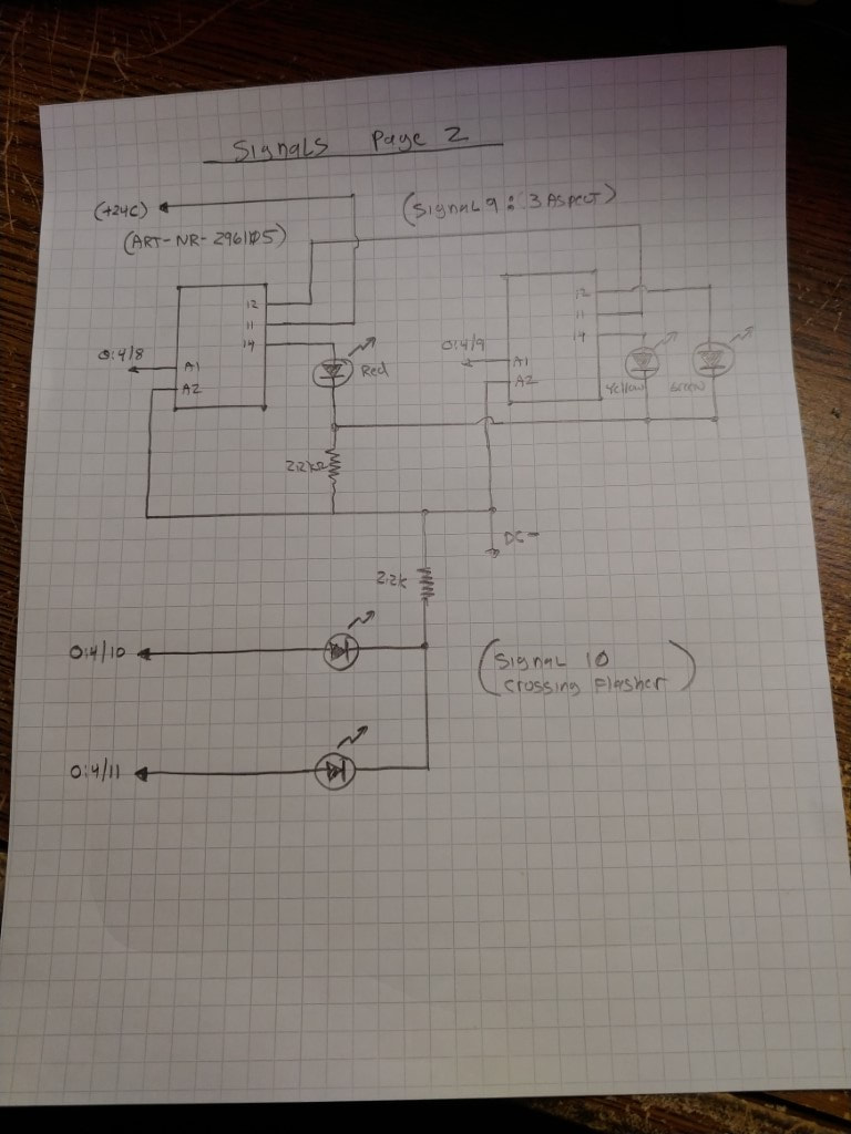
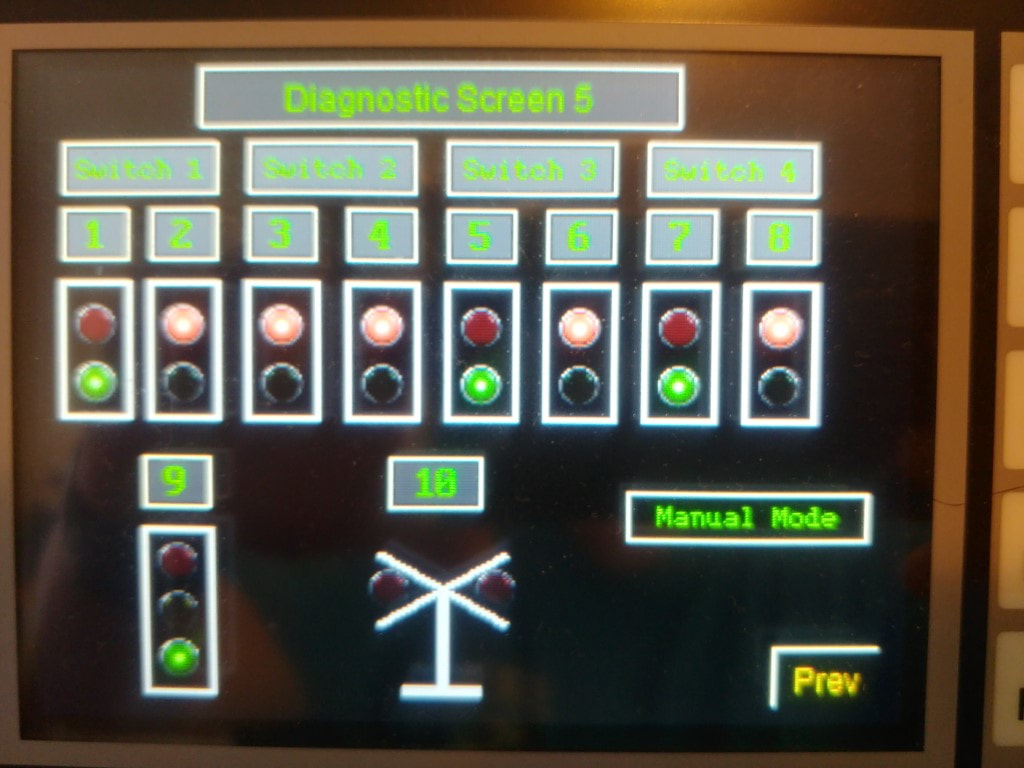
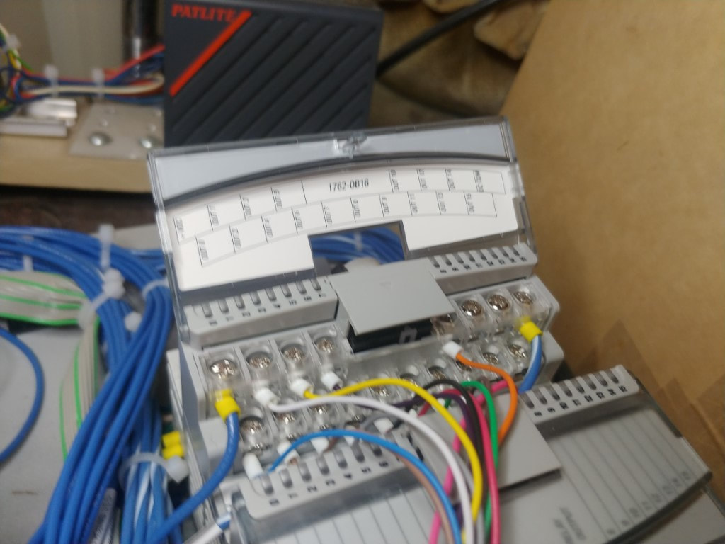
The layout around the wall of my living room has signals. The original plan was to use a similar circuits to control the signals. I found a good used output module on Ebay which can allow the PLC to control the signals. This is the installation of the new module and drawing up the schematics for control of the signals. I also wrote in a new ladder which will also run while control is in manual mode.
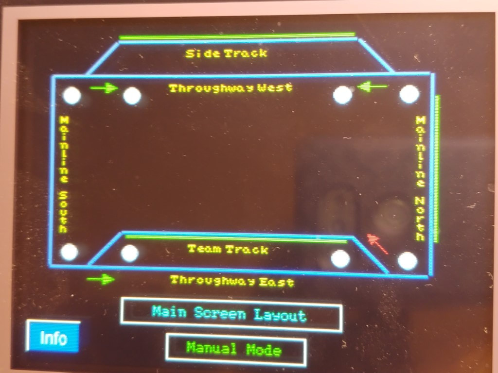
HMI Display of signals (Manual Mode)
Light Tower Modification
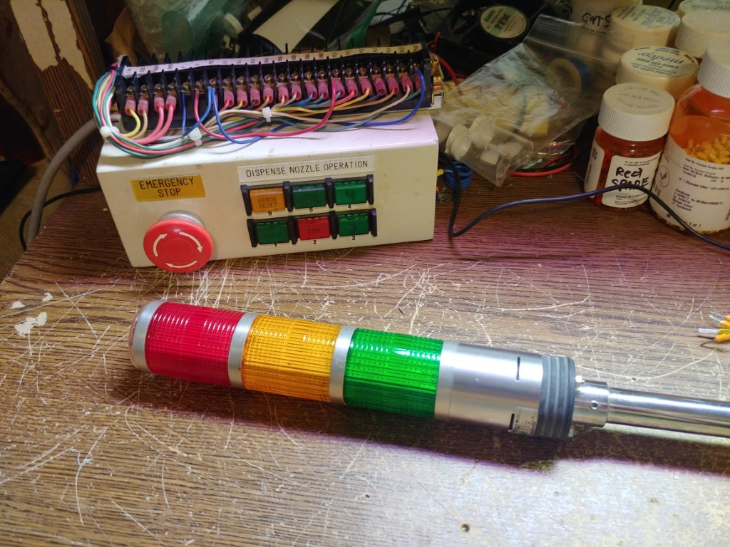
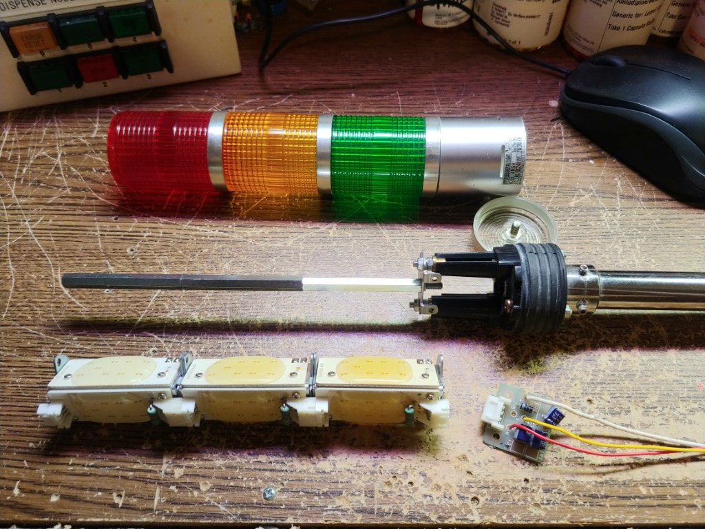
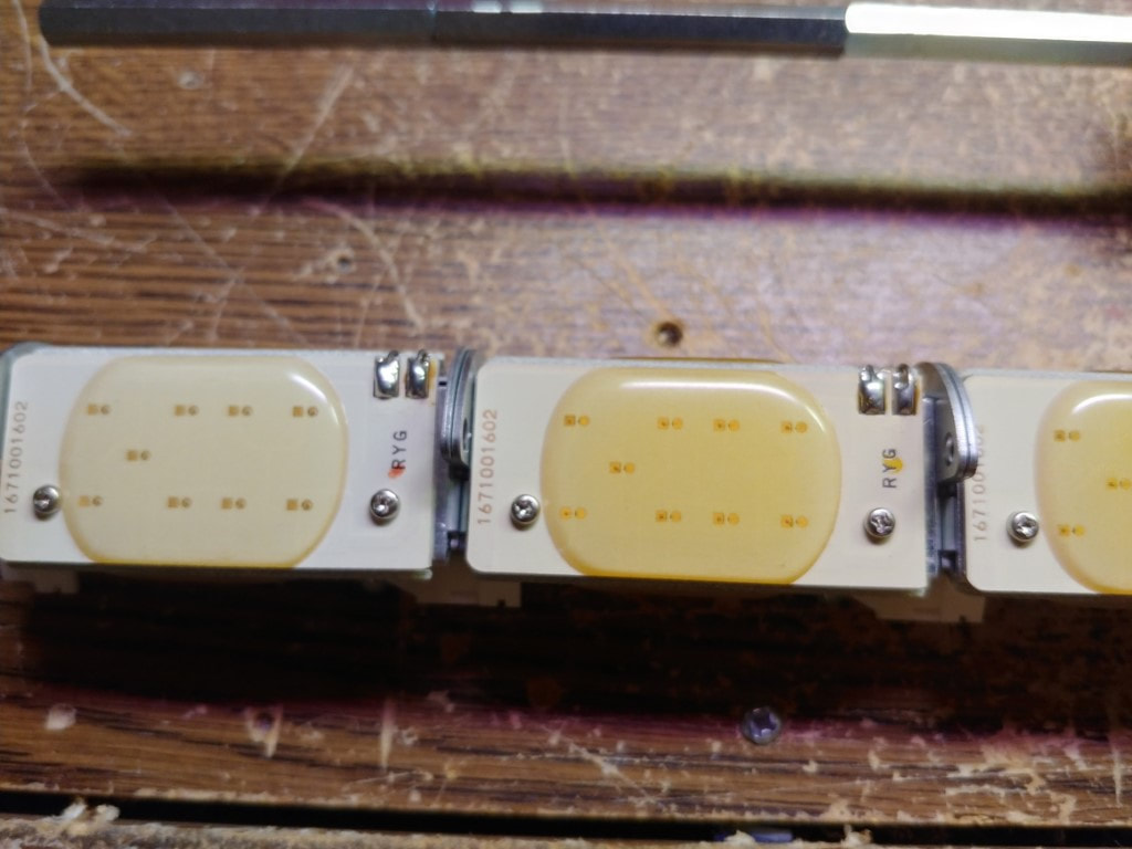
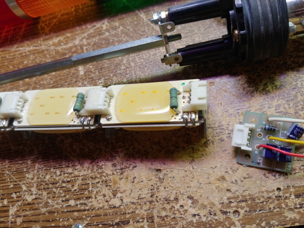
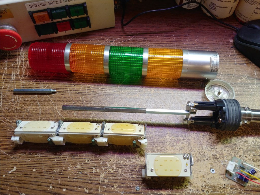
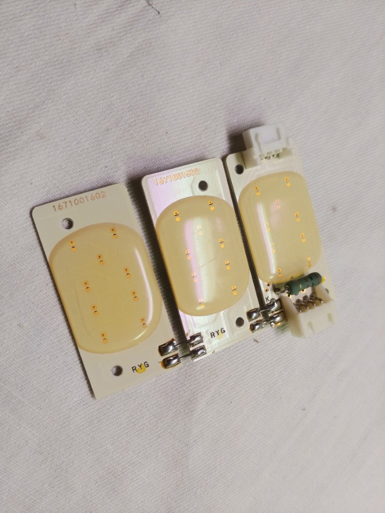
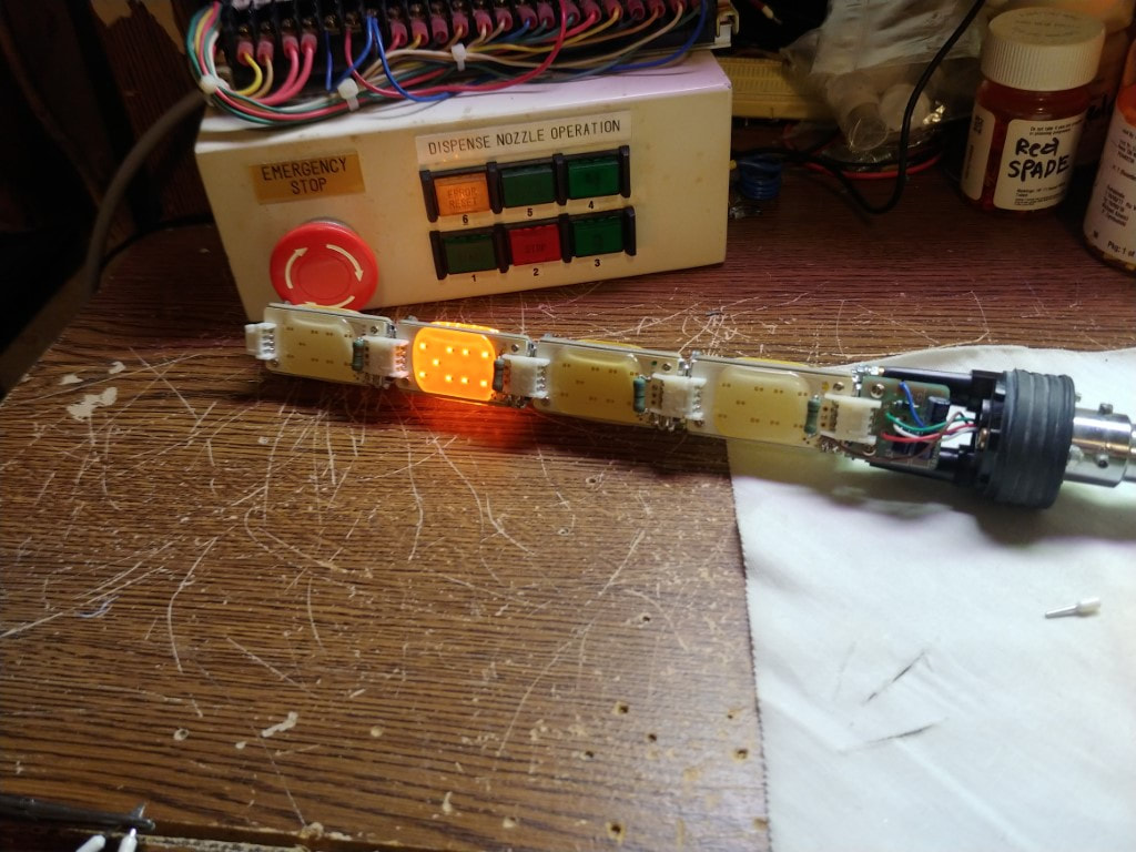
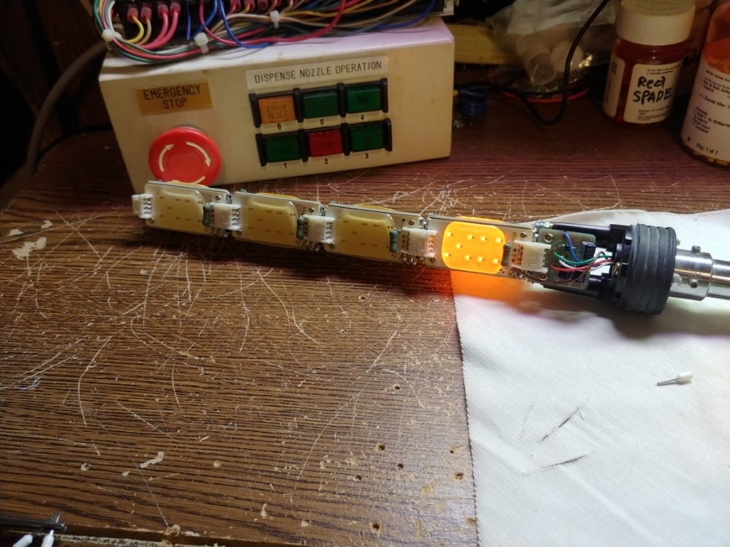
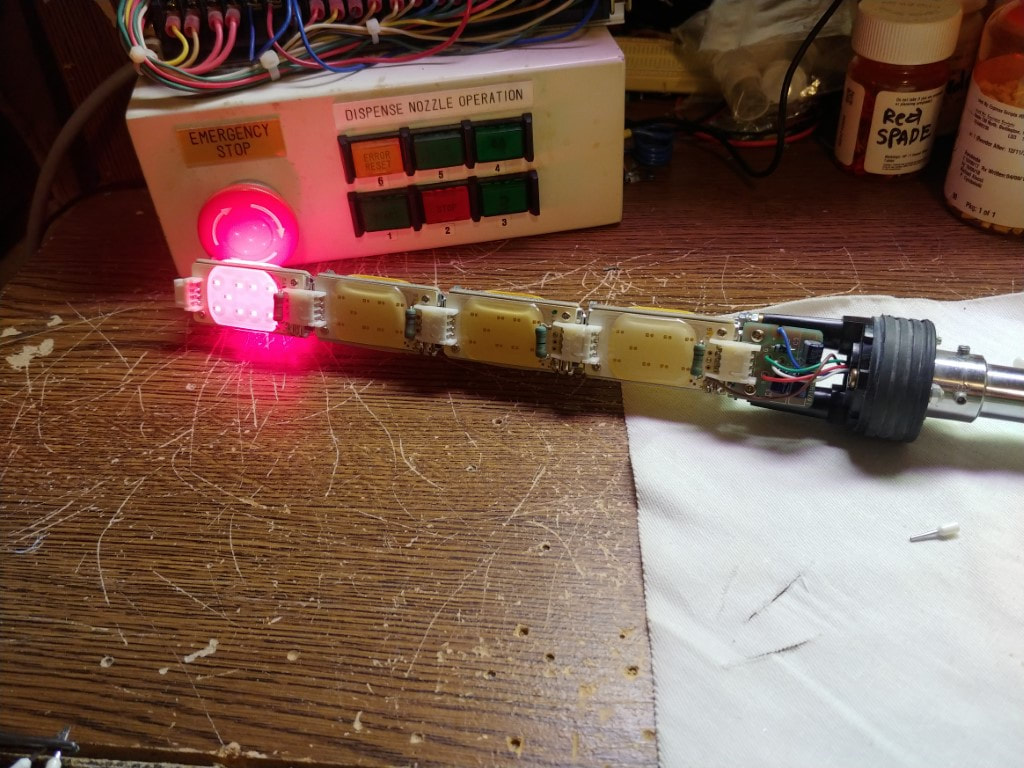
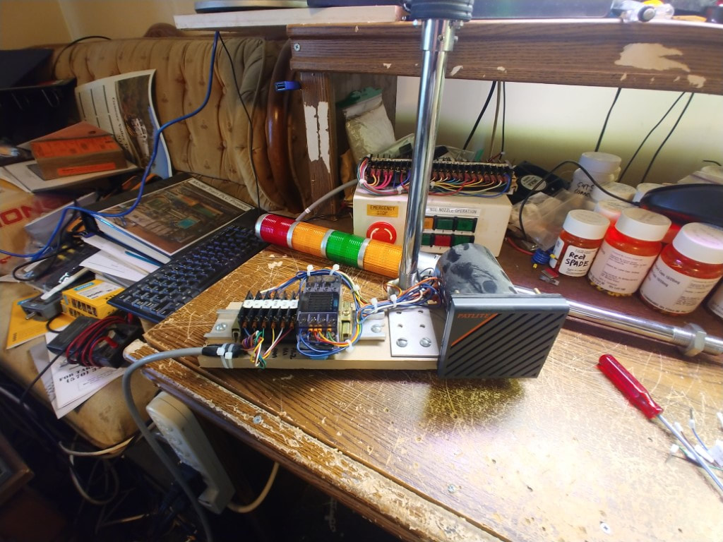
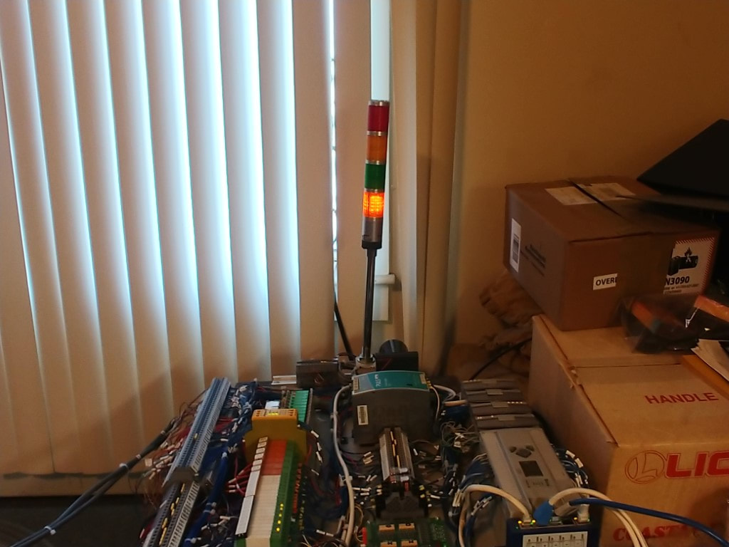
One idea I have is to be able to toggle the audio alarm off or on my PLC control. This way once the project is moved, I can turn off the audio alarm when needed. I wanted a way to still be able to display if a soft or hard alarm has occurred. The soft alarm is still in the developing stages but will be written in later. The current wiring of the tower light does not allow for this. In addition I want to be able to display if the PLC is in automatic or manual mode. The tower lights I have on hand are only three lights. With some work I converted one to have four lights. This way I can display manual/automatic/soft alarm/hard alarm on the tower, and if the emergency stop is pressed, the tower will be dark.
Wiring for signal installation & tower light
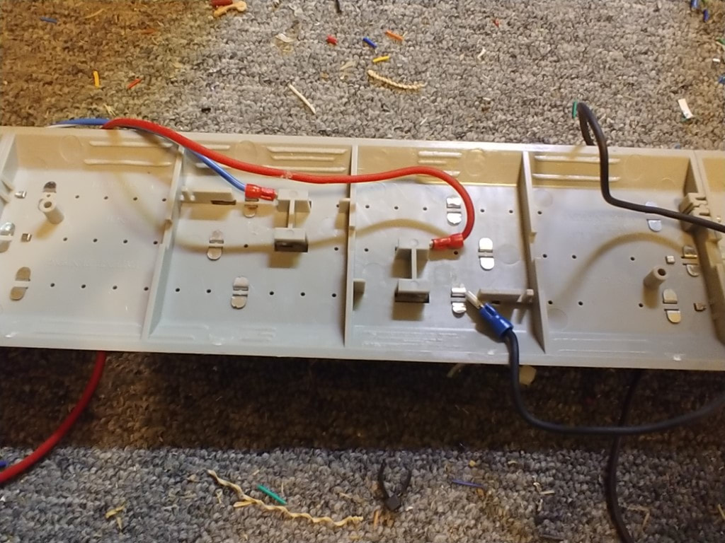
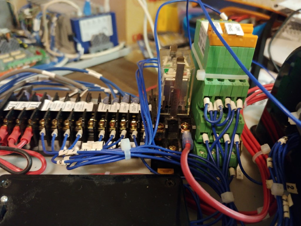
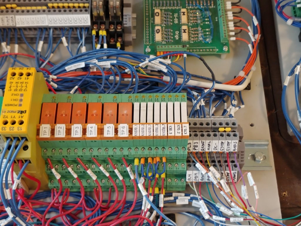
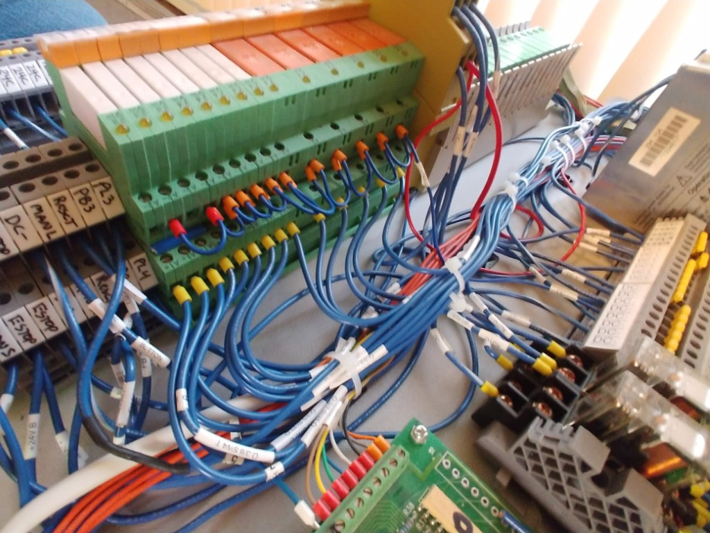
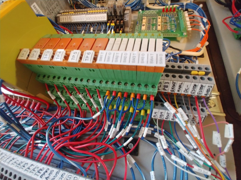
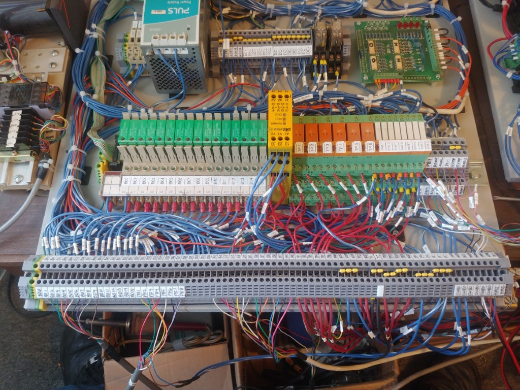
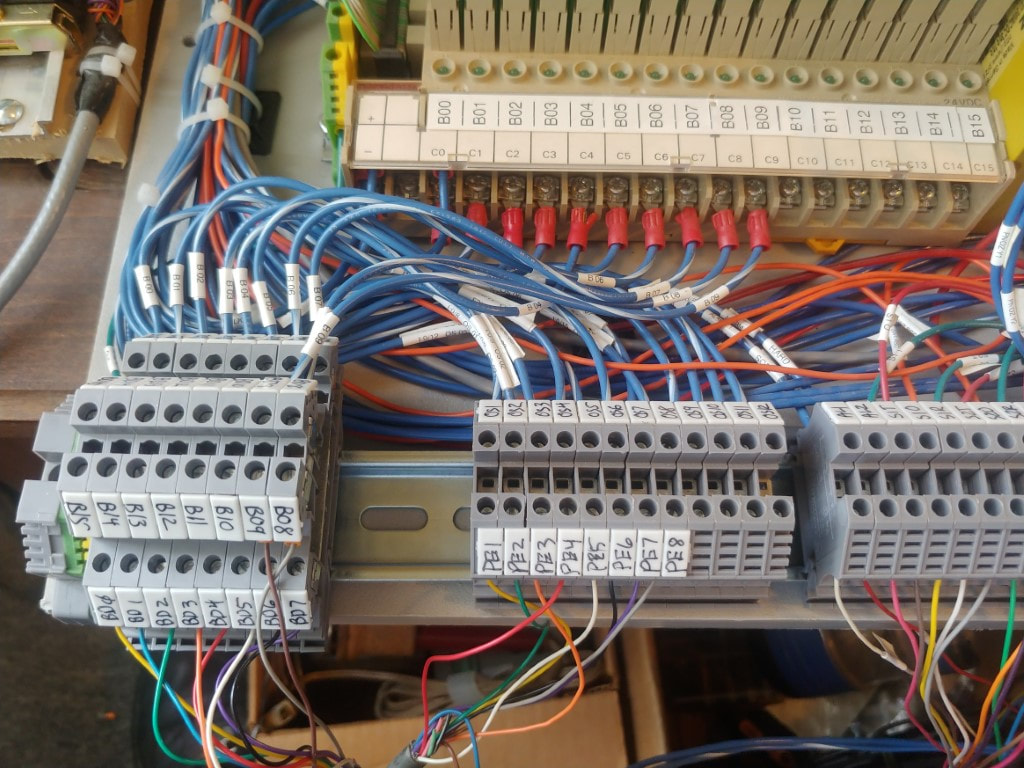
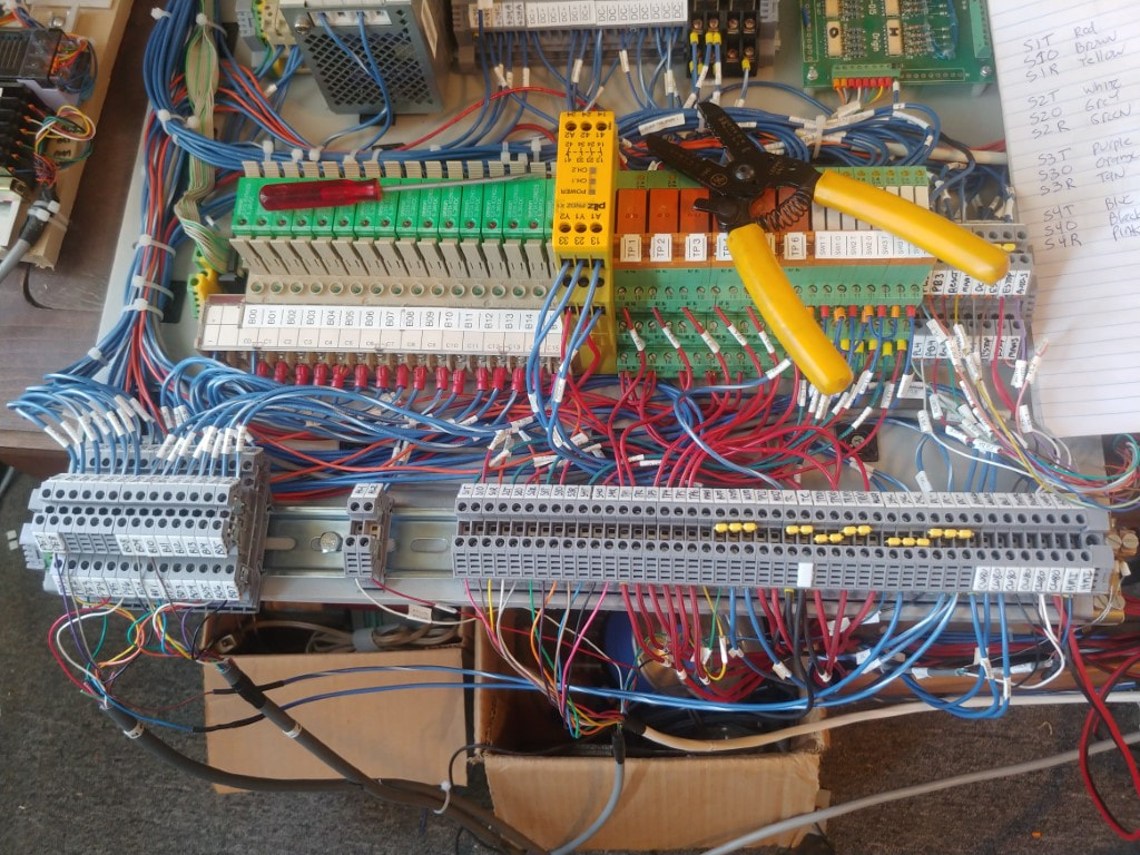
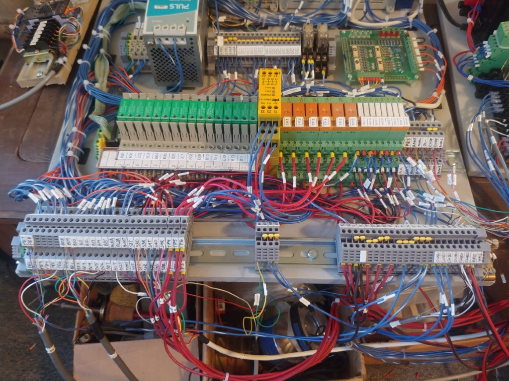
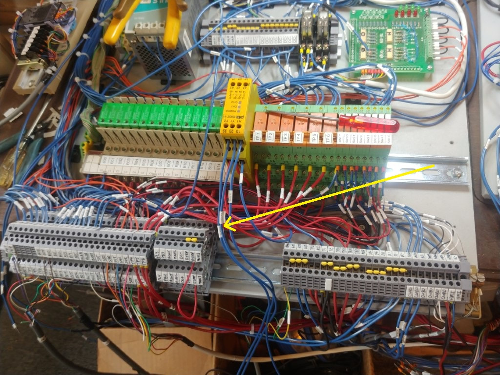
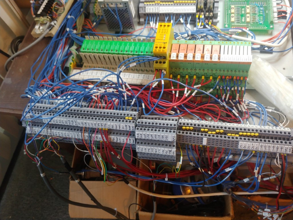
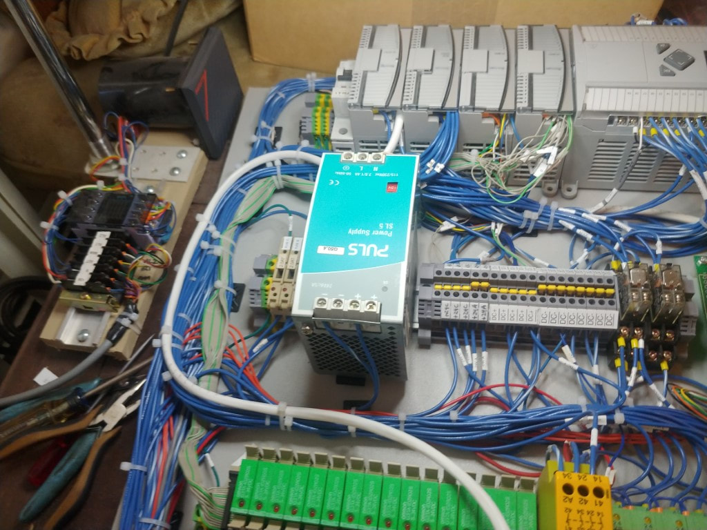
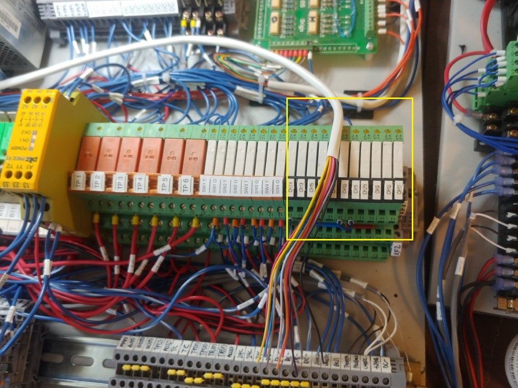
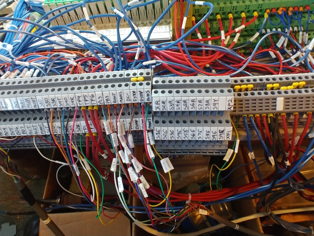
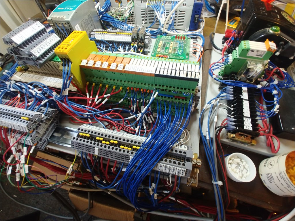
The next series of pictures shows wiring for the installation of the signal control. This involved some changes to the PLC controls to make room for the additional relays needed and replacing some of the terminal blocks with double stacked ones. The modified tower light was also installed which now separates the tower light alarms to the audio alarms.
Mainline / Side / Team Alternating Run Routine
This routine allows all three trains to run the mainline one at a time for a set number of laps. As with the other alternating routines, this one will run endless. In this demonstration video, the blue RS-3 unit messed up with its direction control.
Side & Team Interchange
This routine will physically interchange the trains that are parked on the side track and the team track. Since there is usually a train on the mainline, extra steps are taken to avoid fouling the mainline. There is provision for this routine to skip some steps if there is no train on the mainline. For this video demonstration, a train is running on the mainline as the starting point. This was the most complex routine written so far.
Analog Control of CW80 Transformer
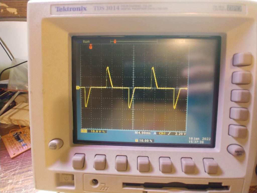
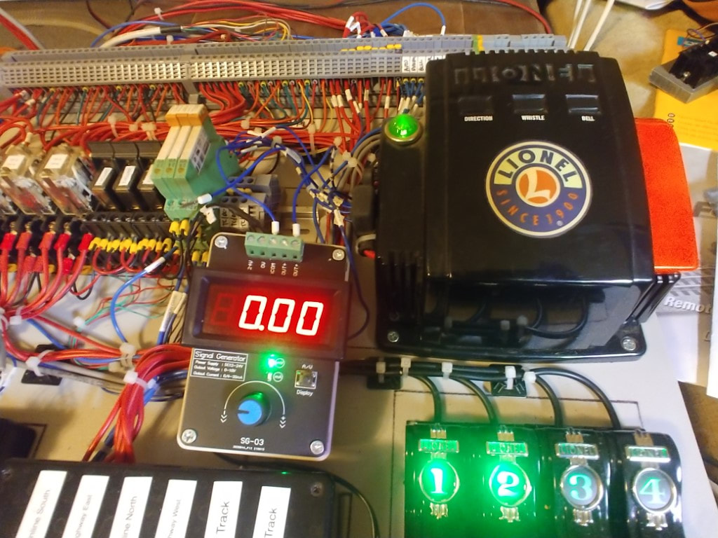
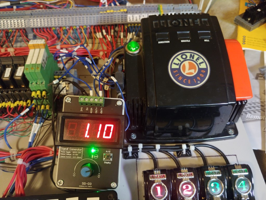
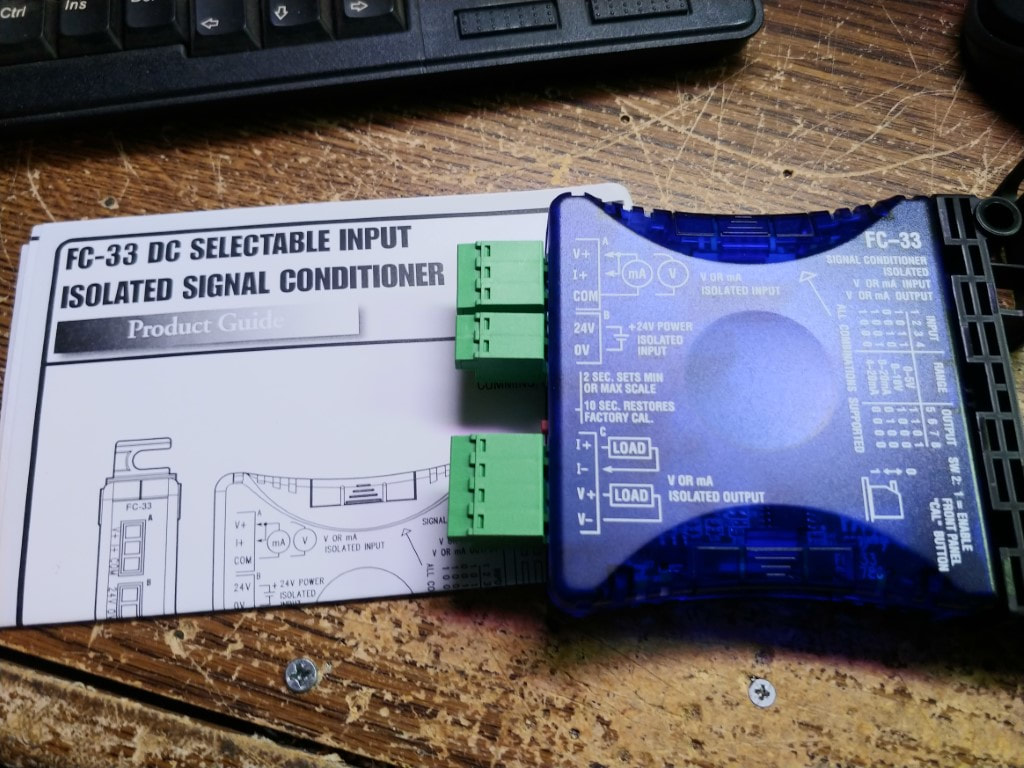
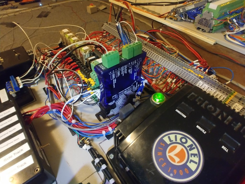
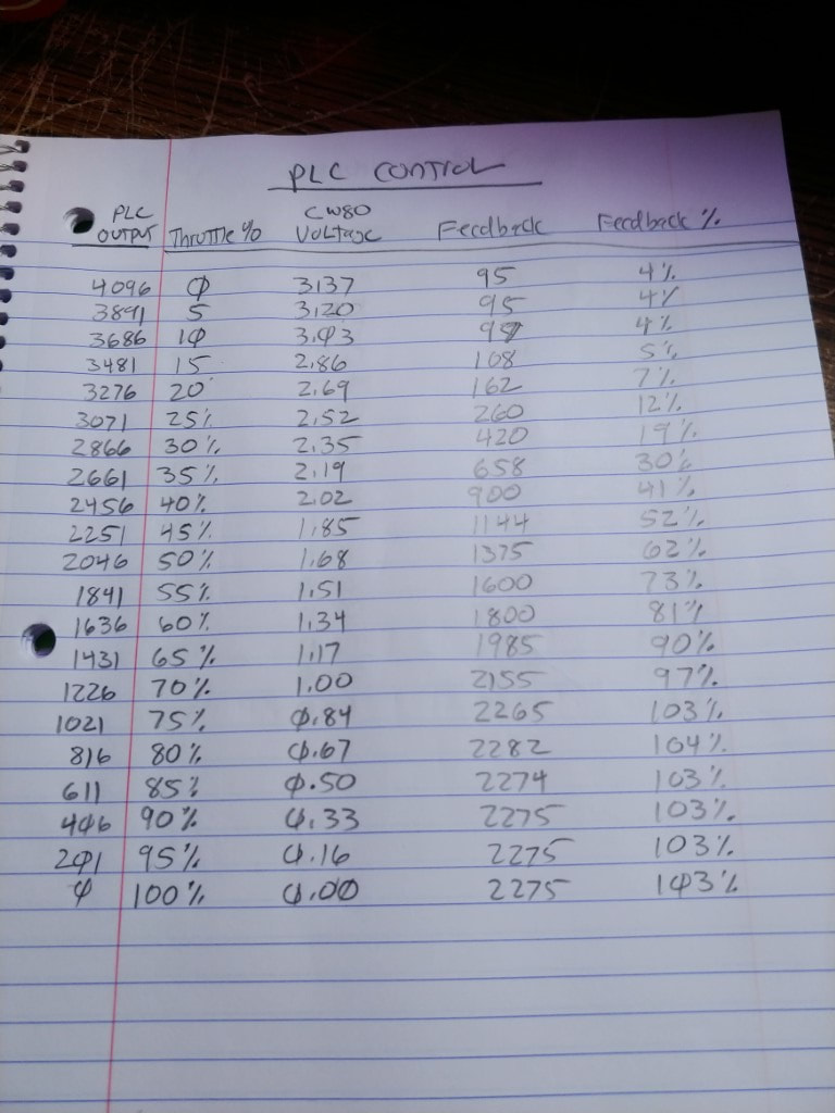
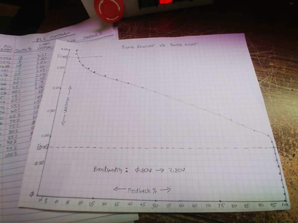
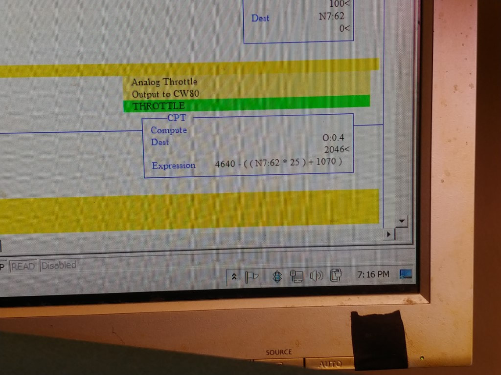
The next step was to utilize the analog capability of the PLC to control the CW80 Transformer for automatic throttle control. One problem I ran into was connecting to the dc input from the throttle wiper. I have DC- connected to track common for block detection and when I connected to the common of the wiper, it caused a short circuit. The solution was to purchase a signal isolation which worked out well. It took some experimenting with the CW80 since the AC output is not a clean sine wave but a triac output. This does cause some difference in the feedback from the transformer to measure the throttle output. This is being used more to sense in the event of a derailment of overload the transformer shutting down its output as a protection.
