Programmable Logic Controller Project
First Generation
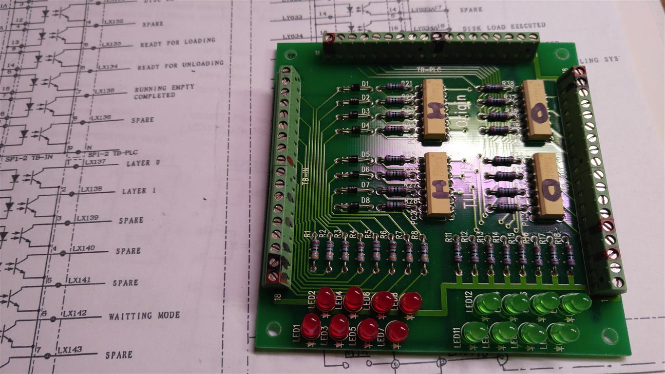
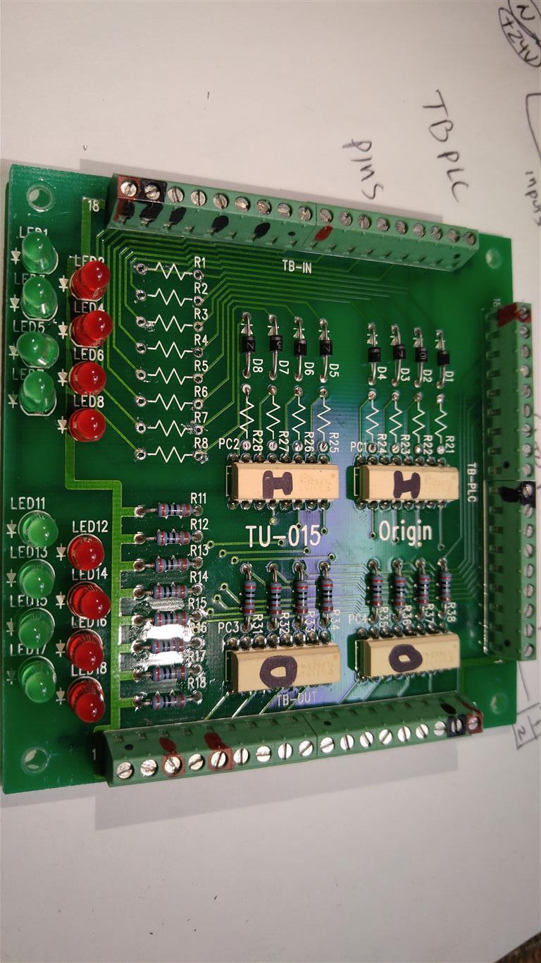
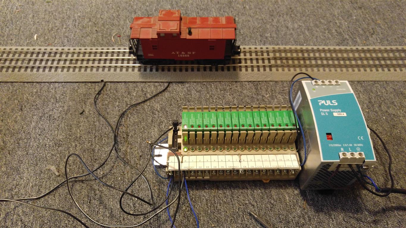
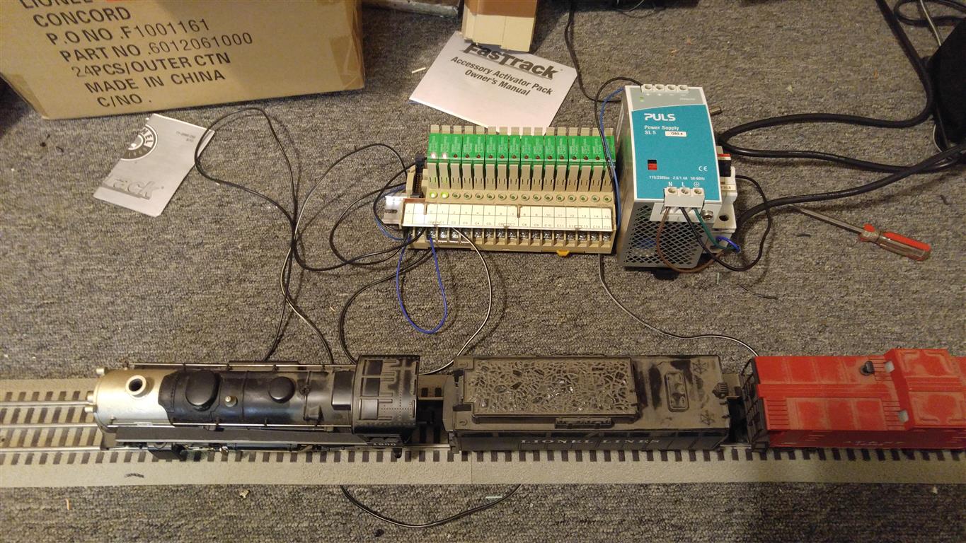
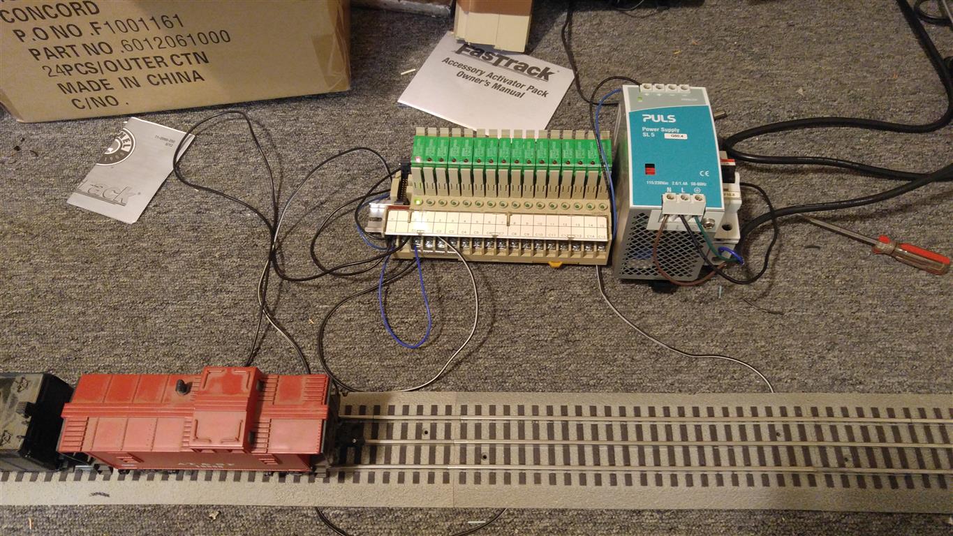
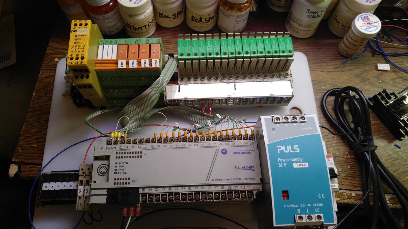
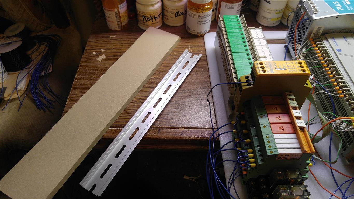
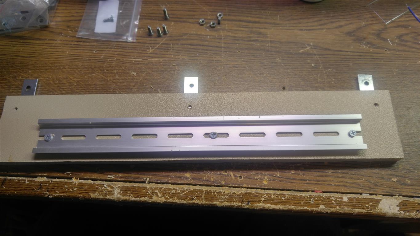
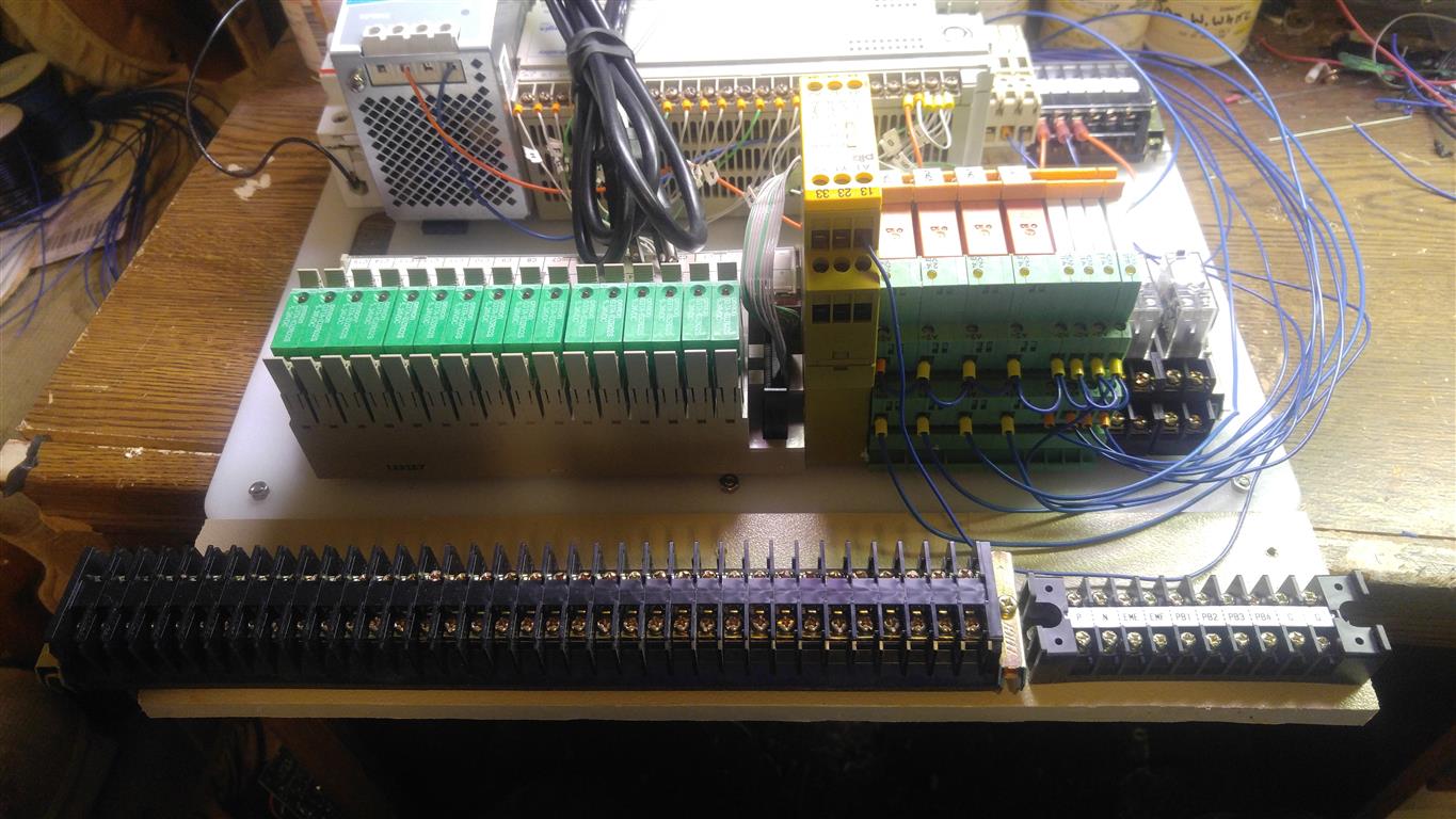
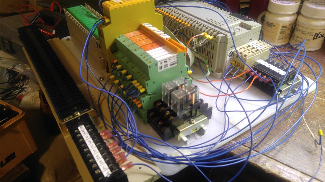
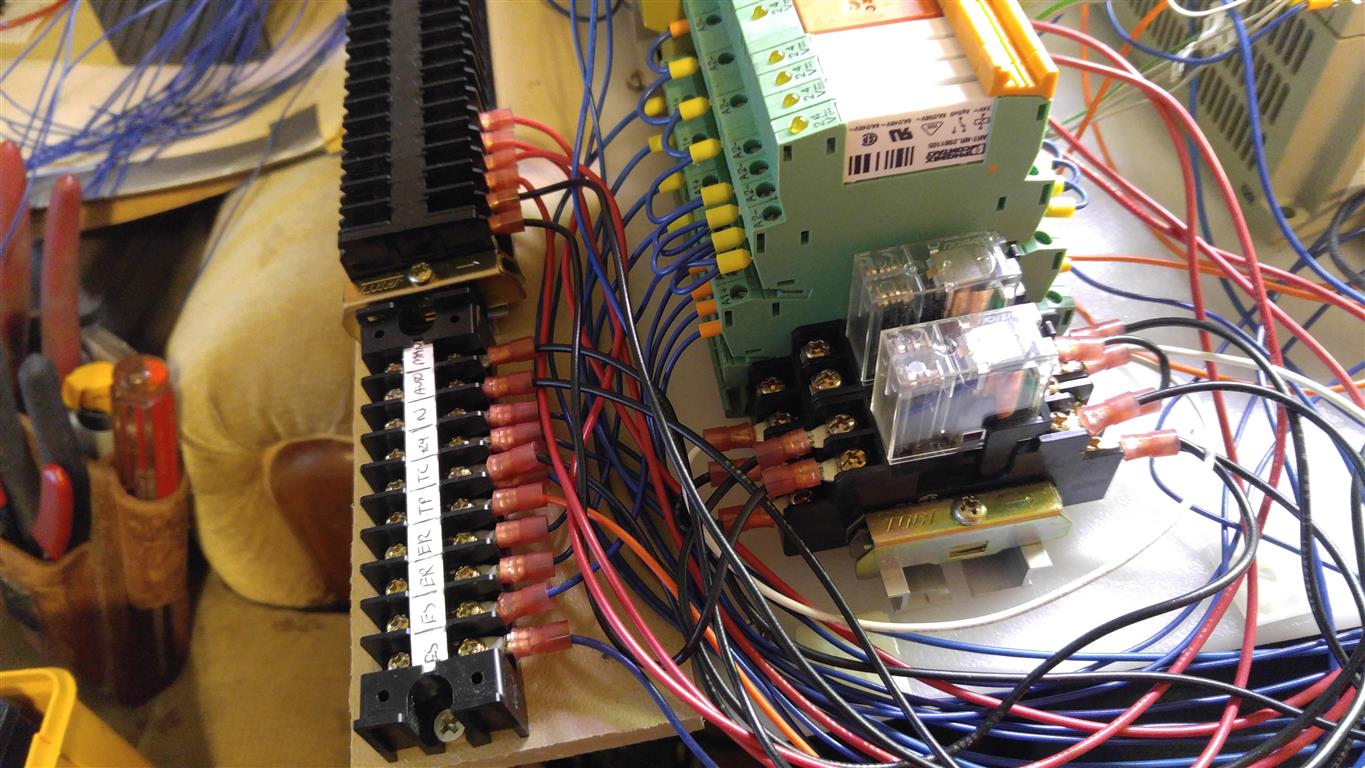
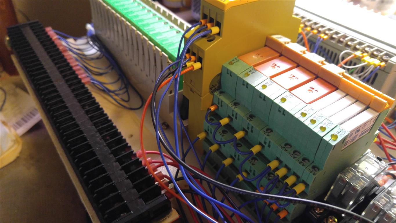
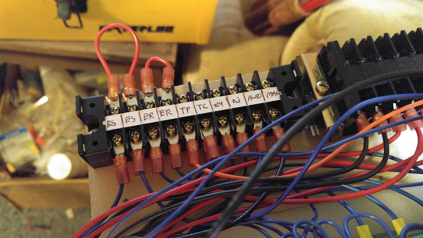
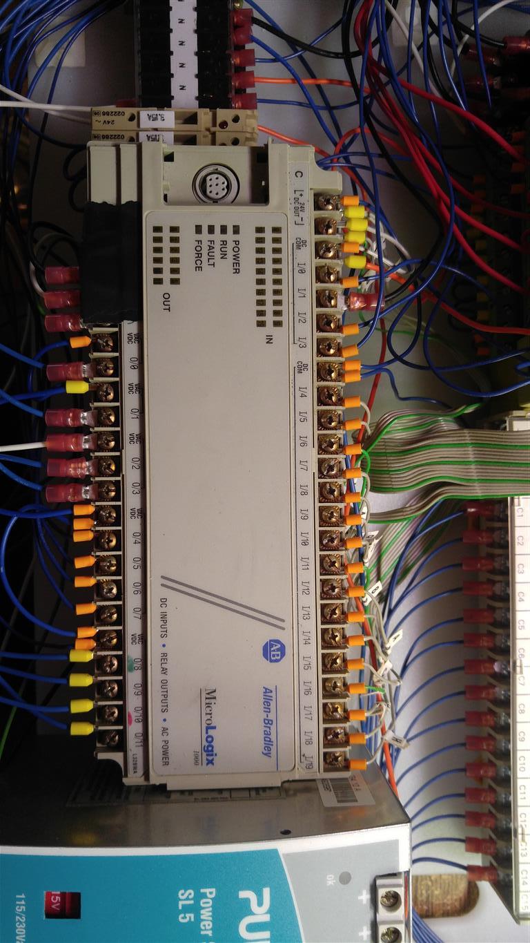
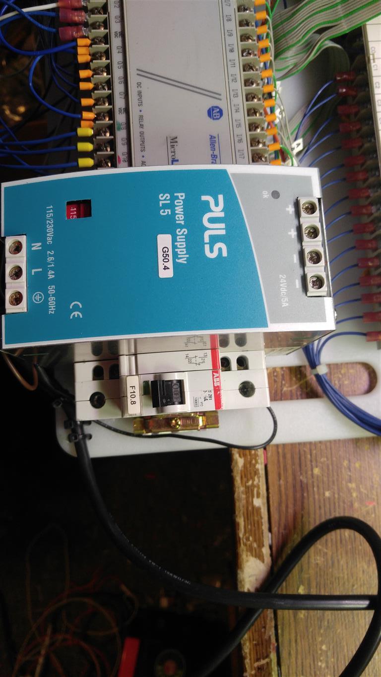
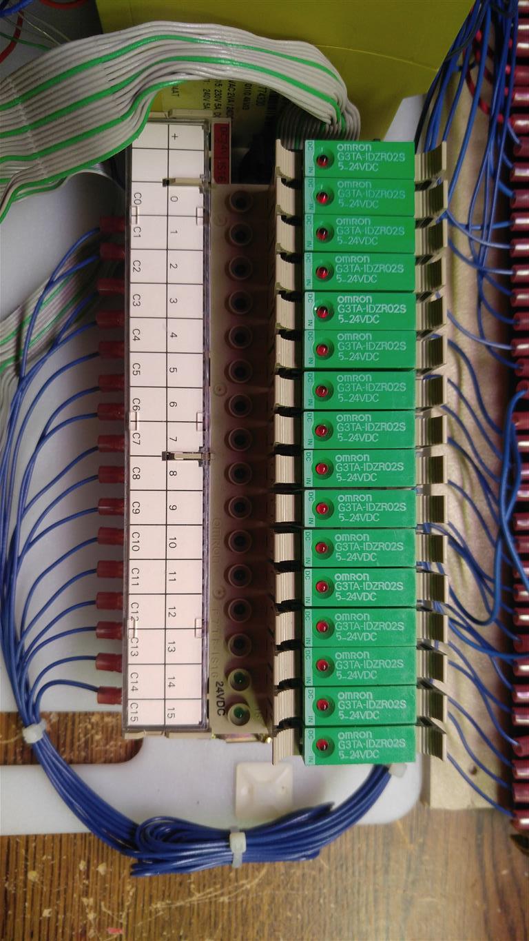
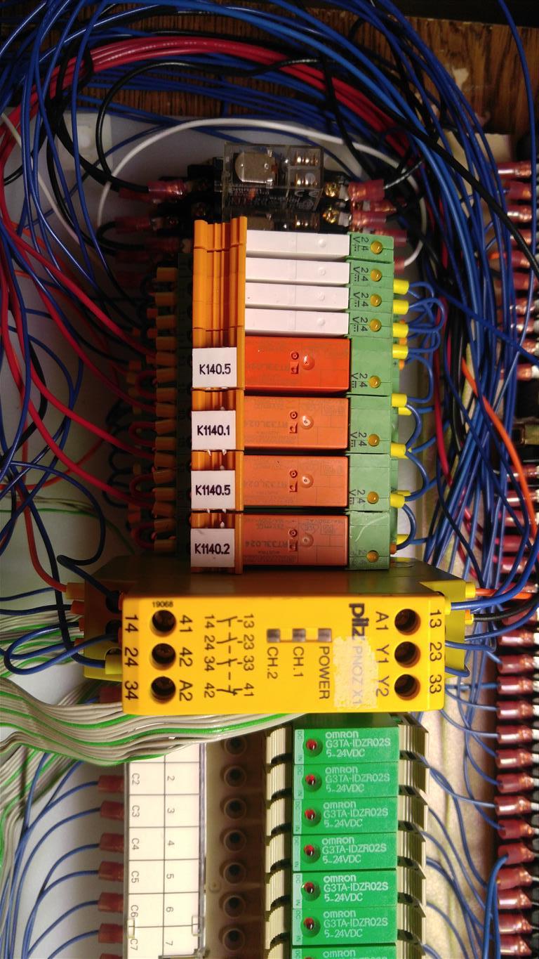
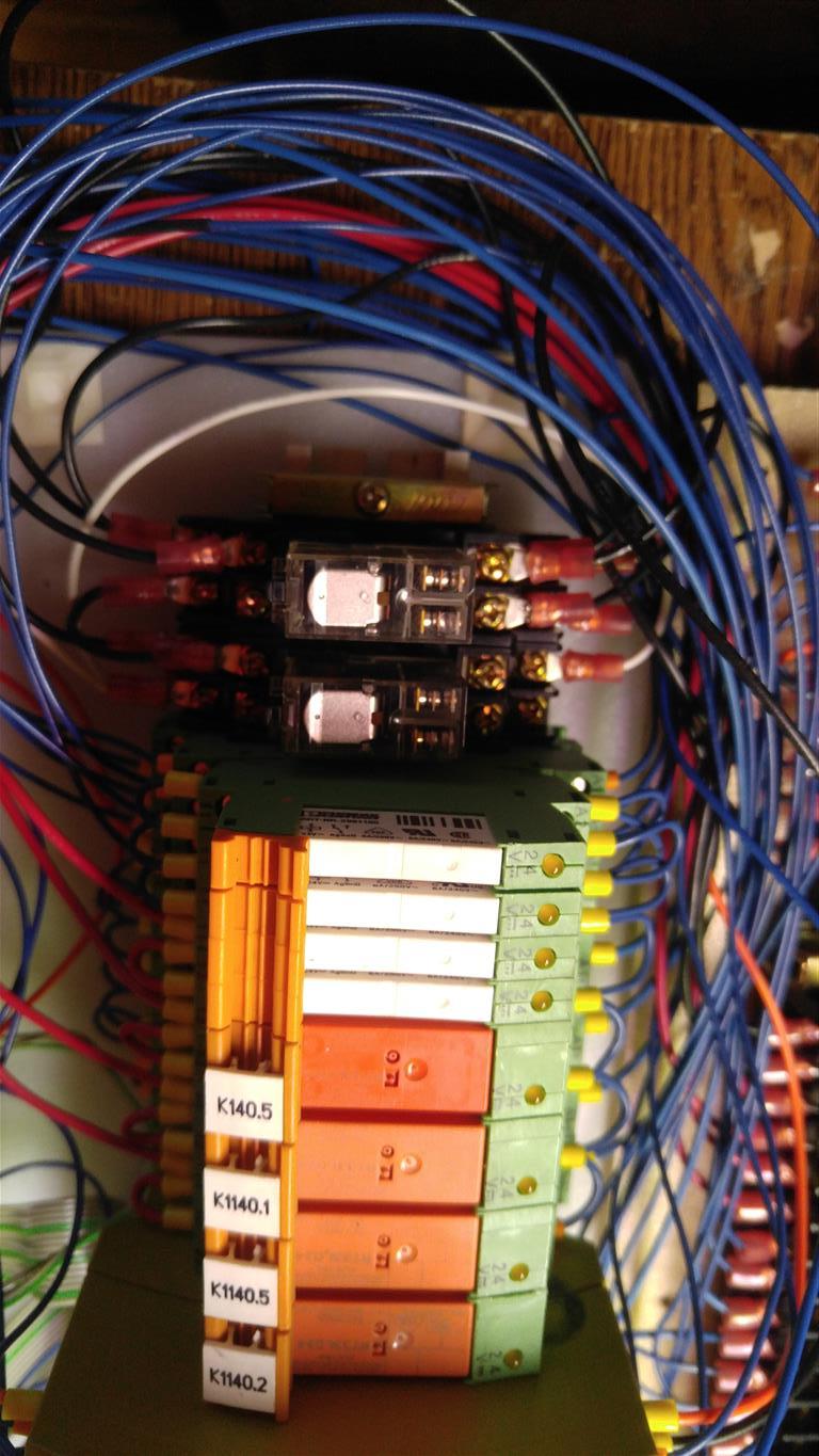
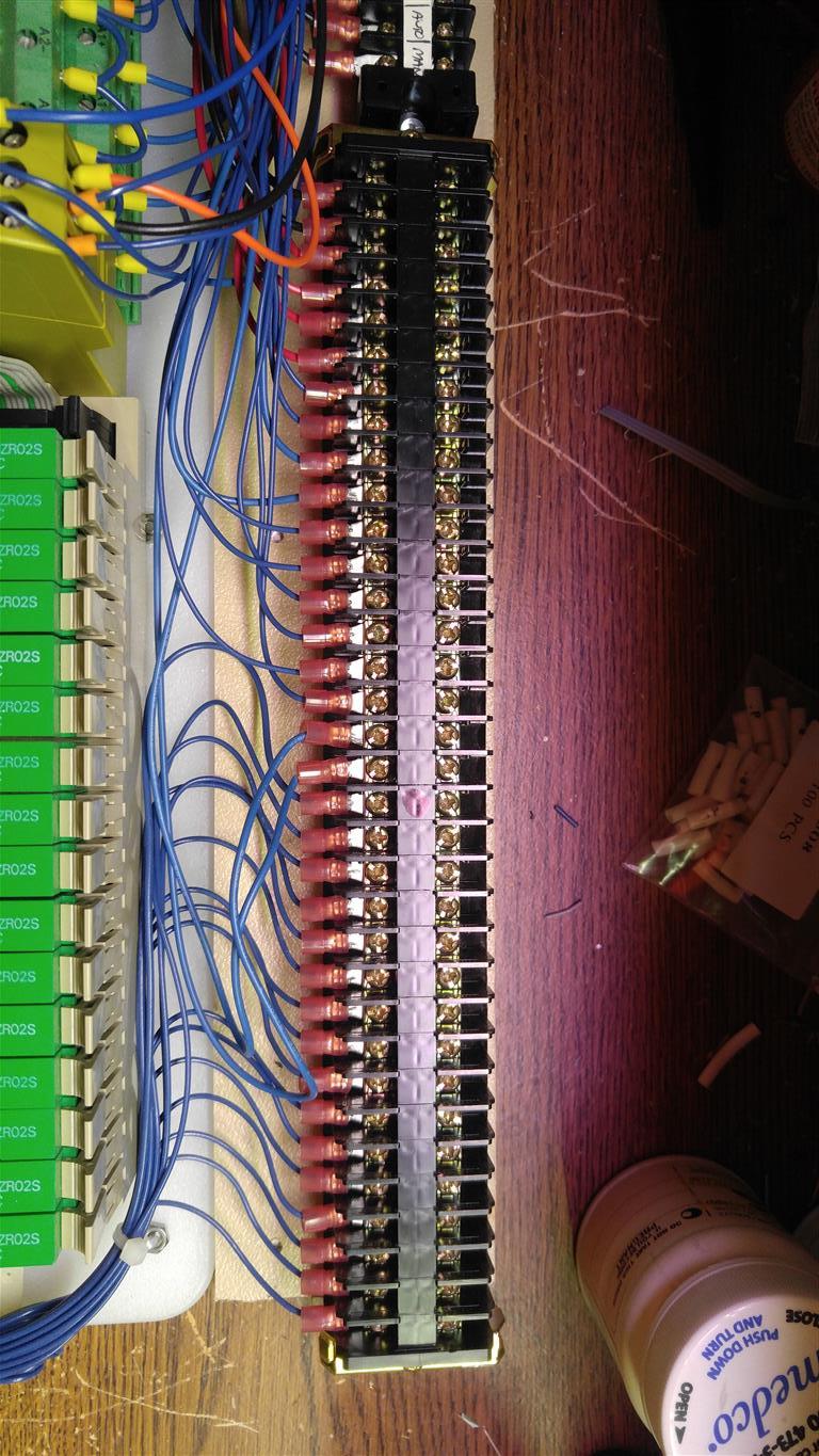
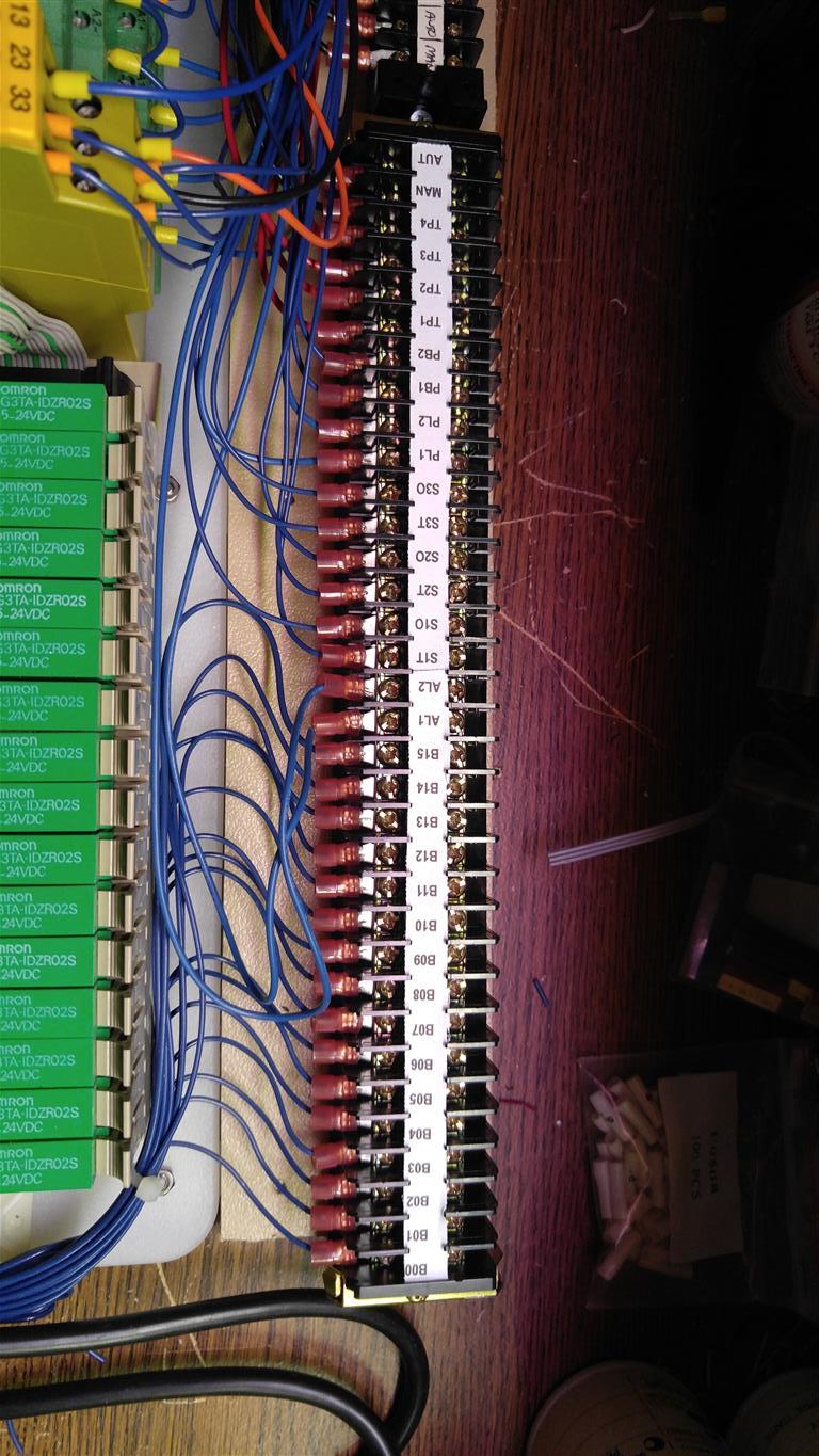
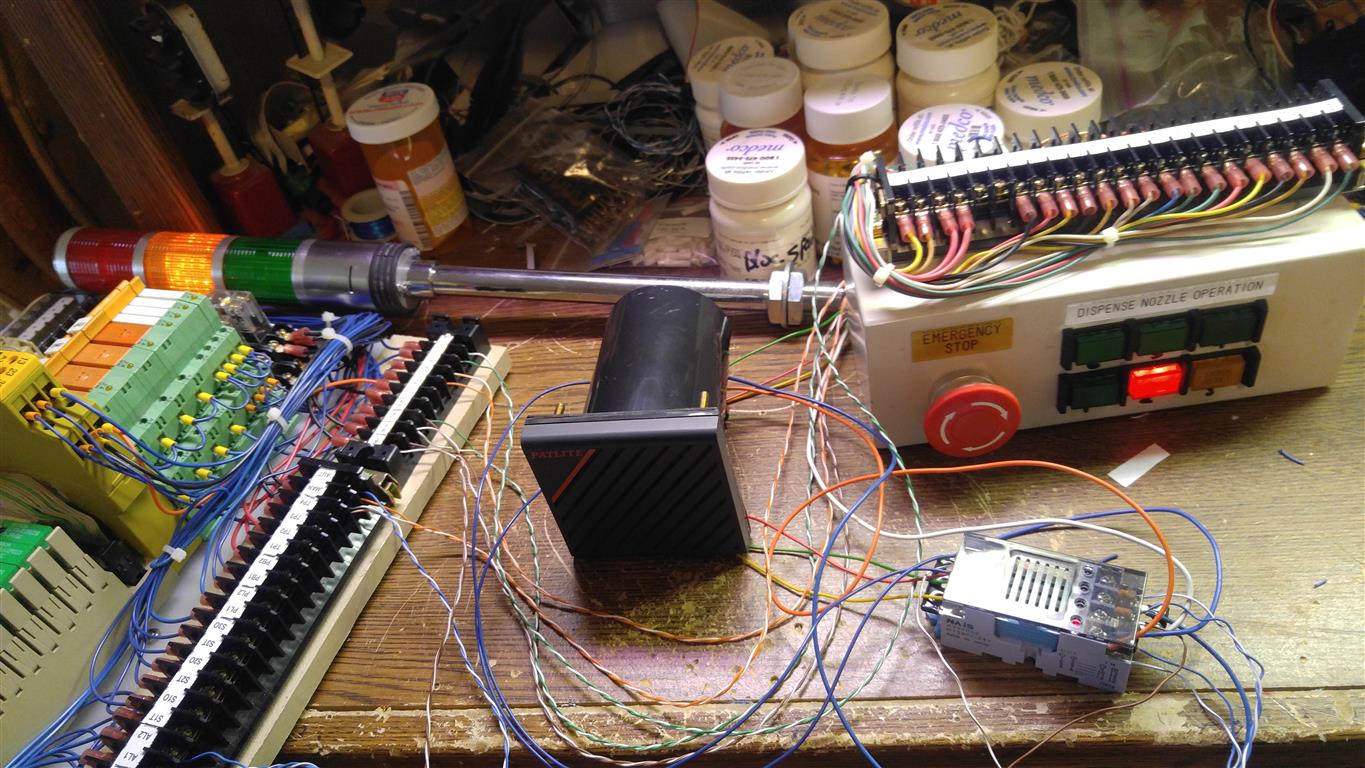
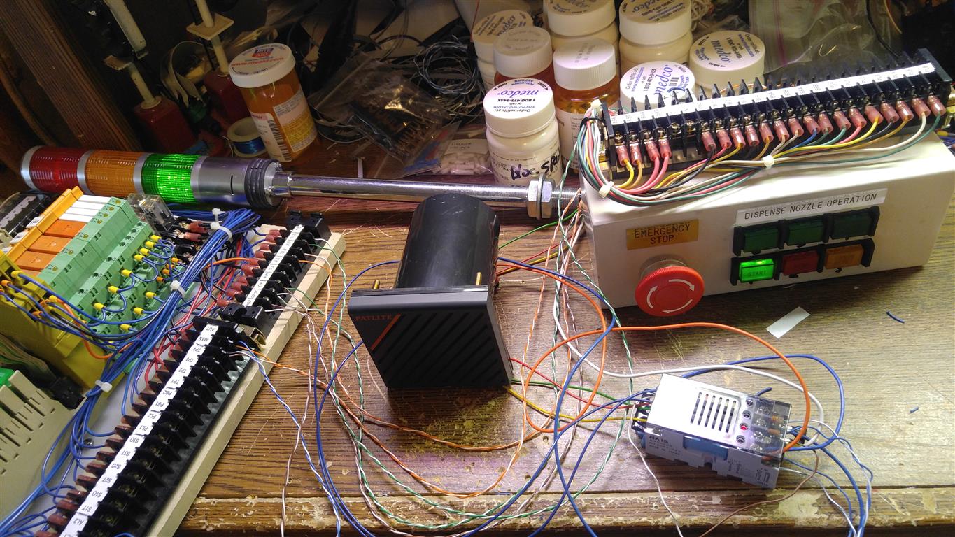
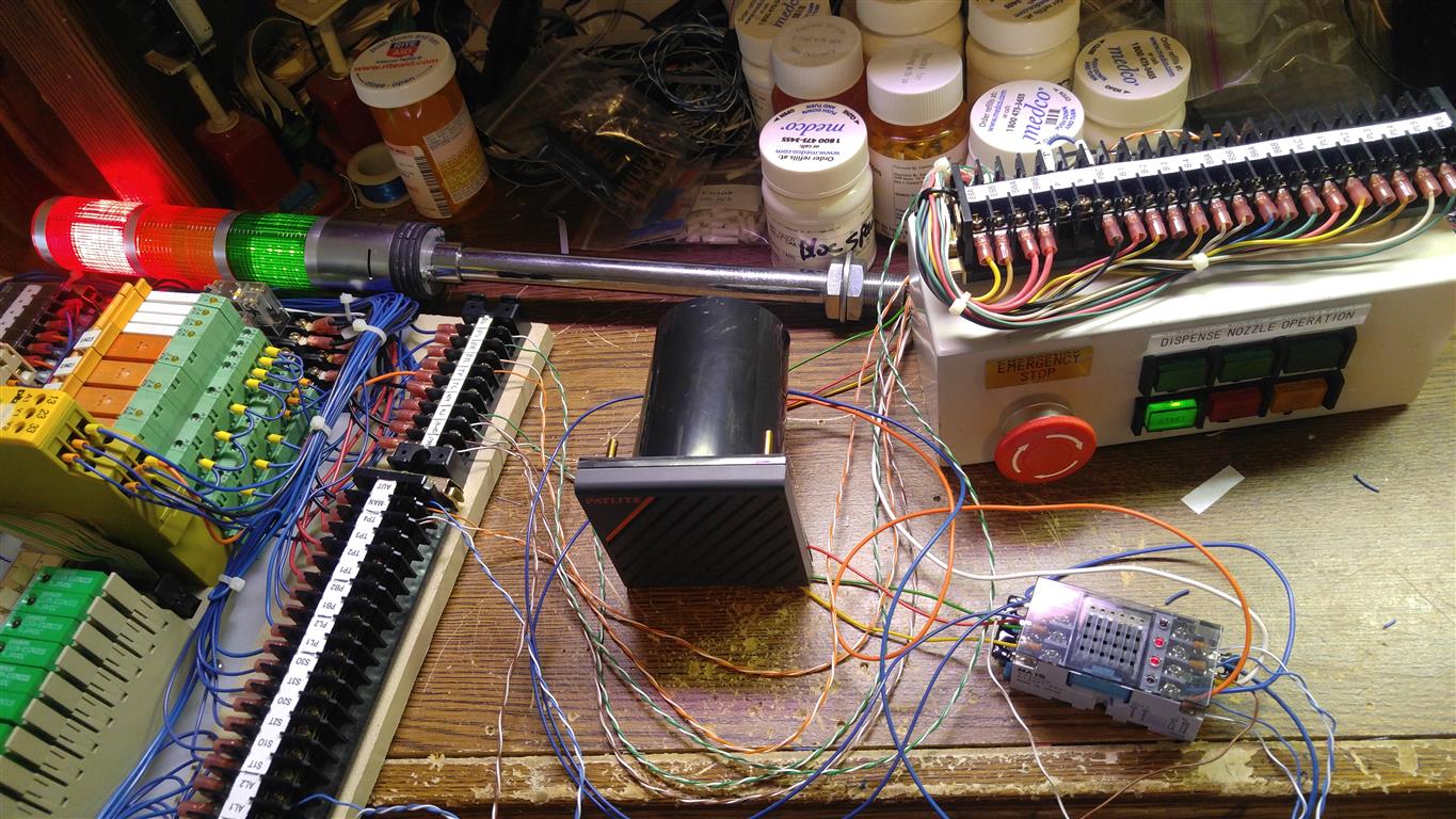
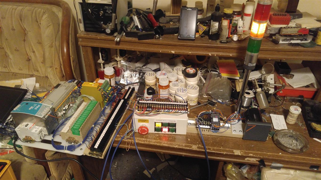
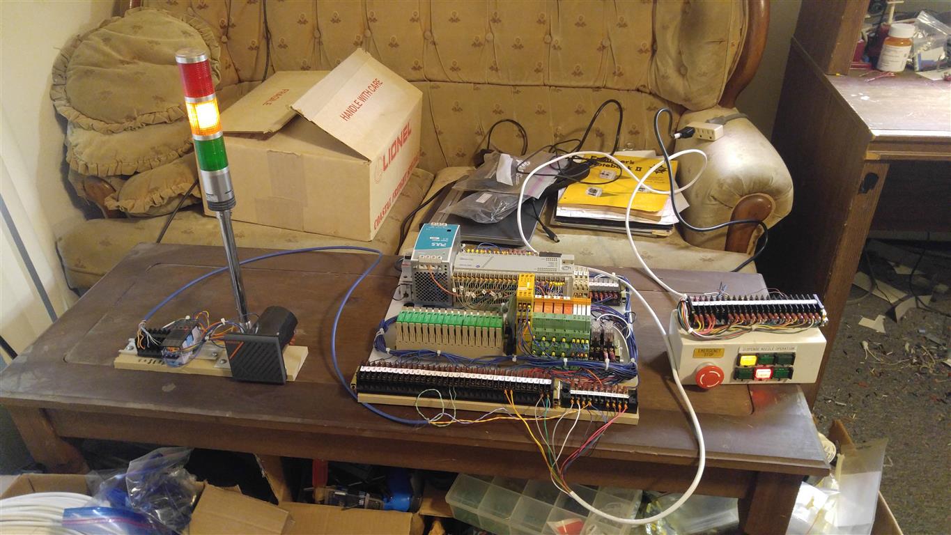
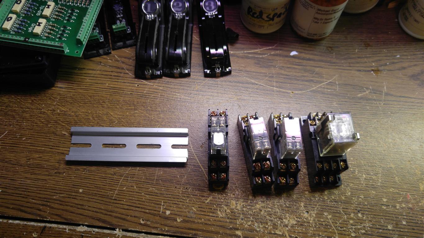
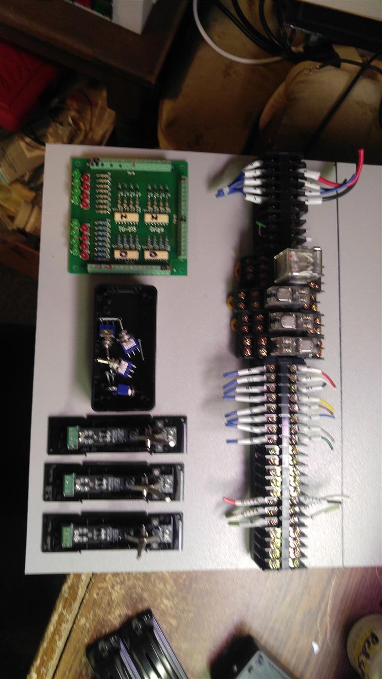
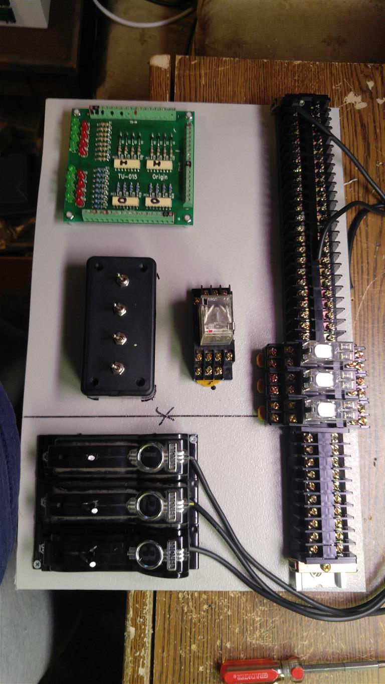
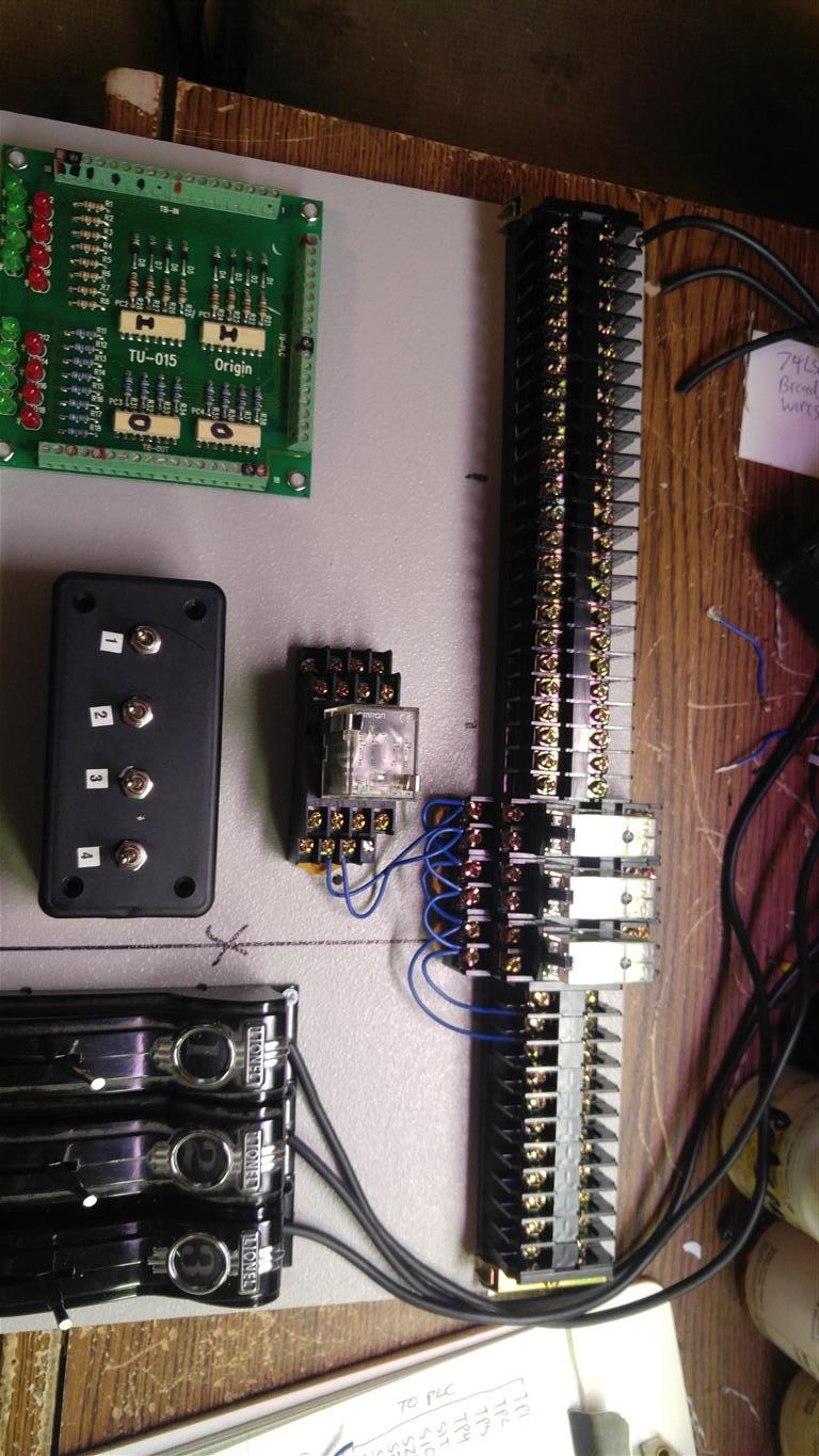
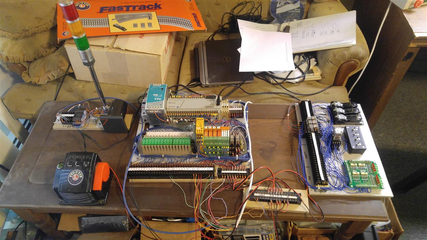
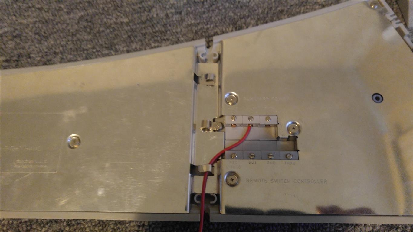
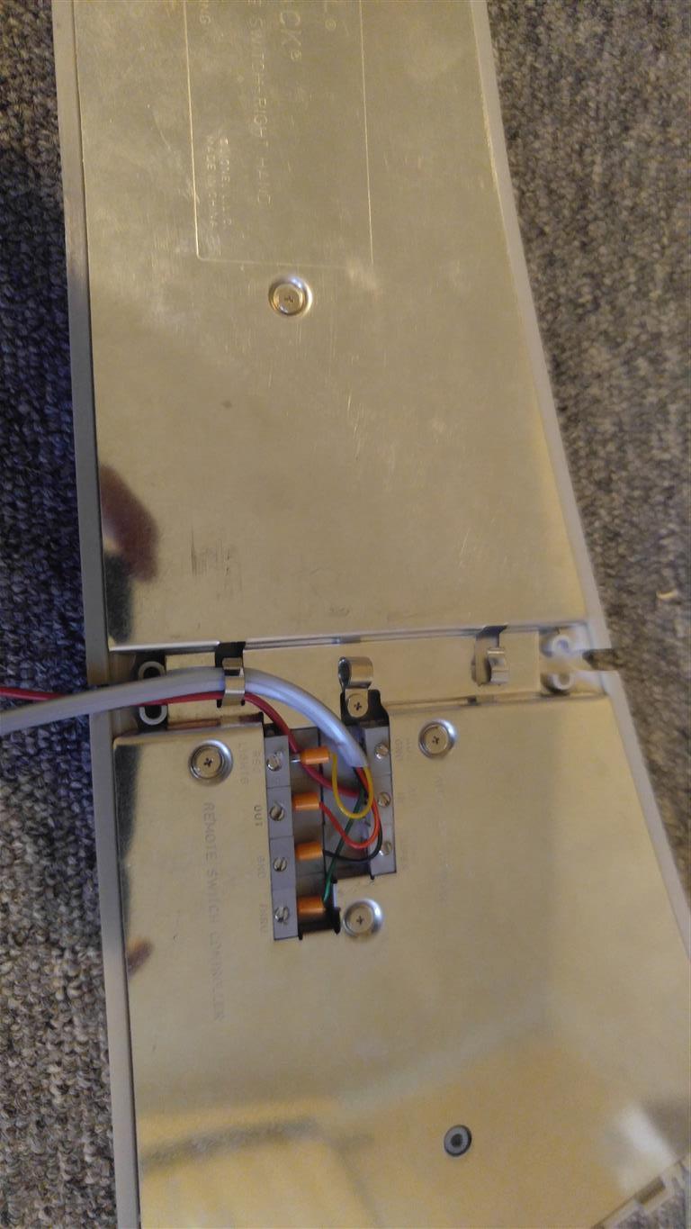
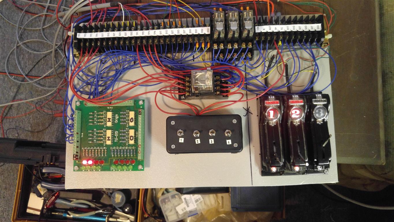
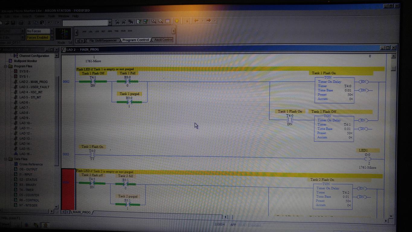
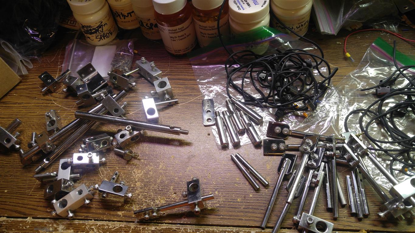
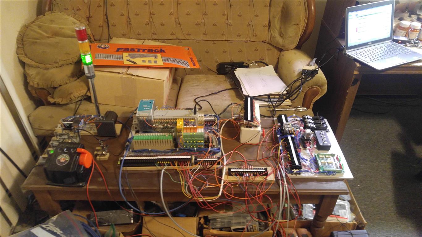
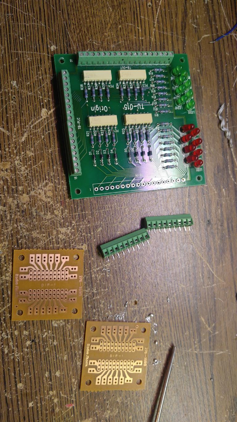
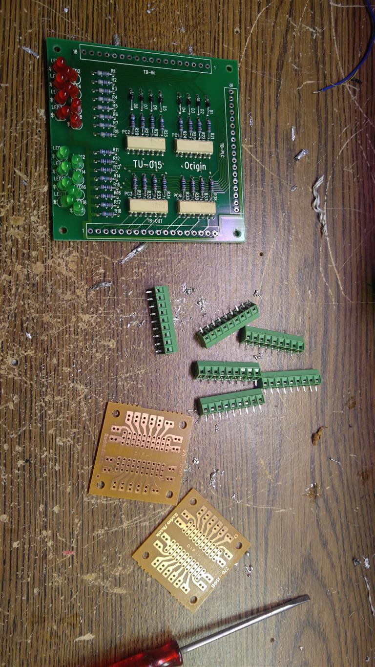
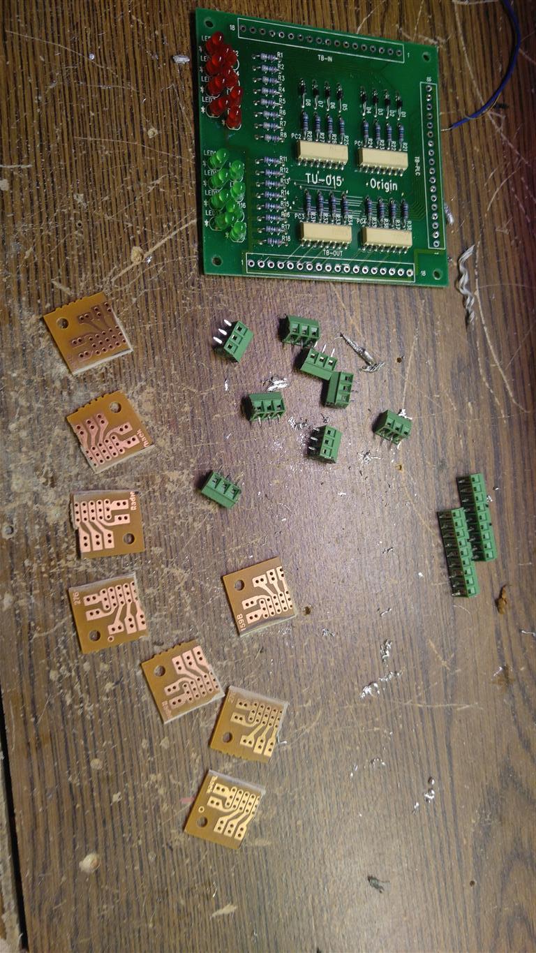
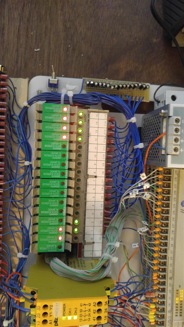
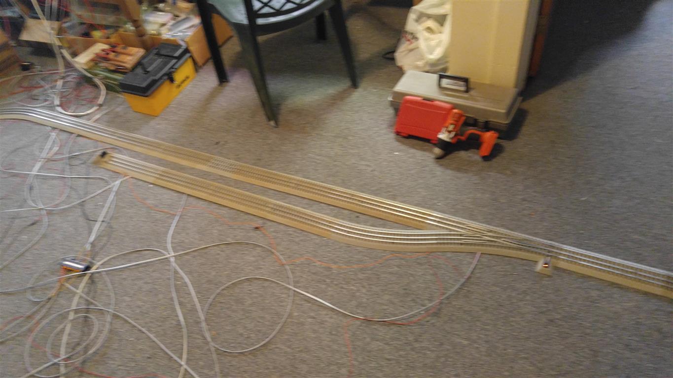
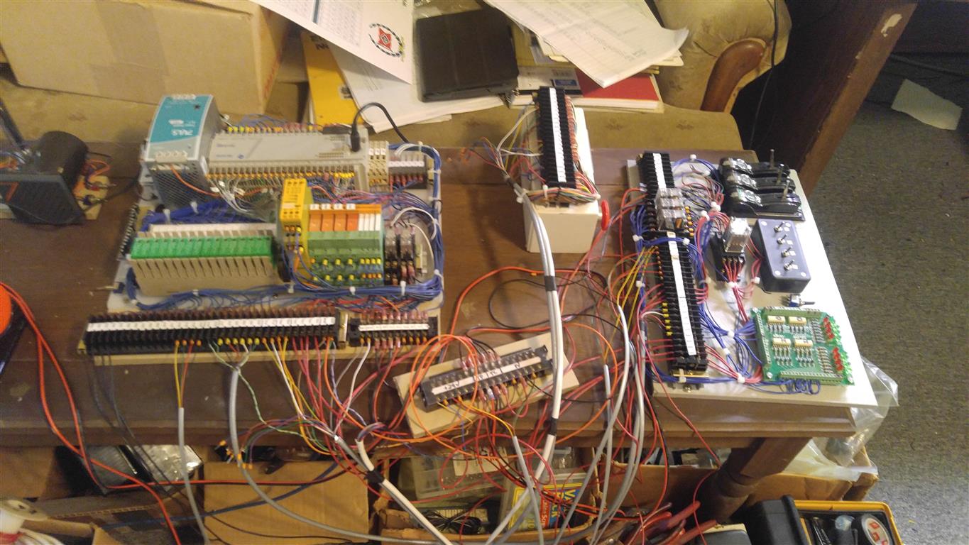
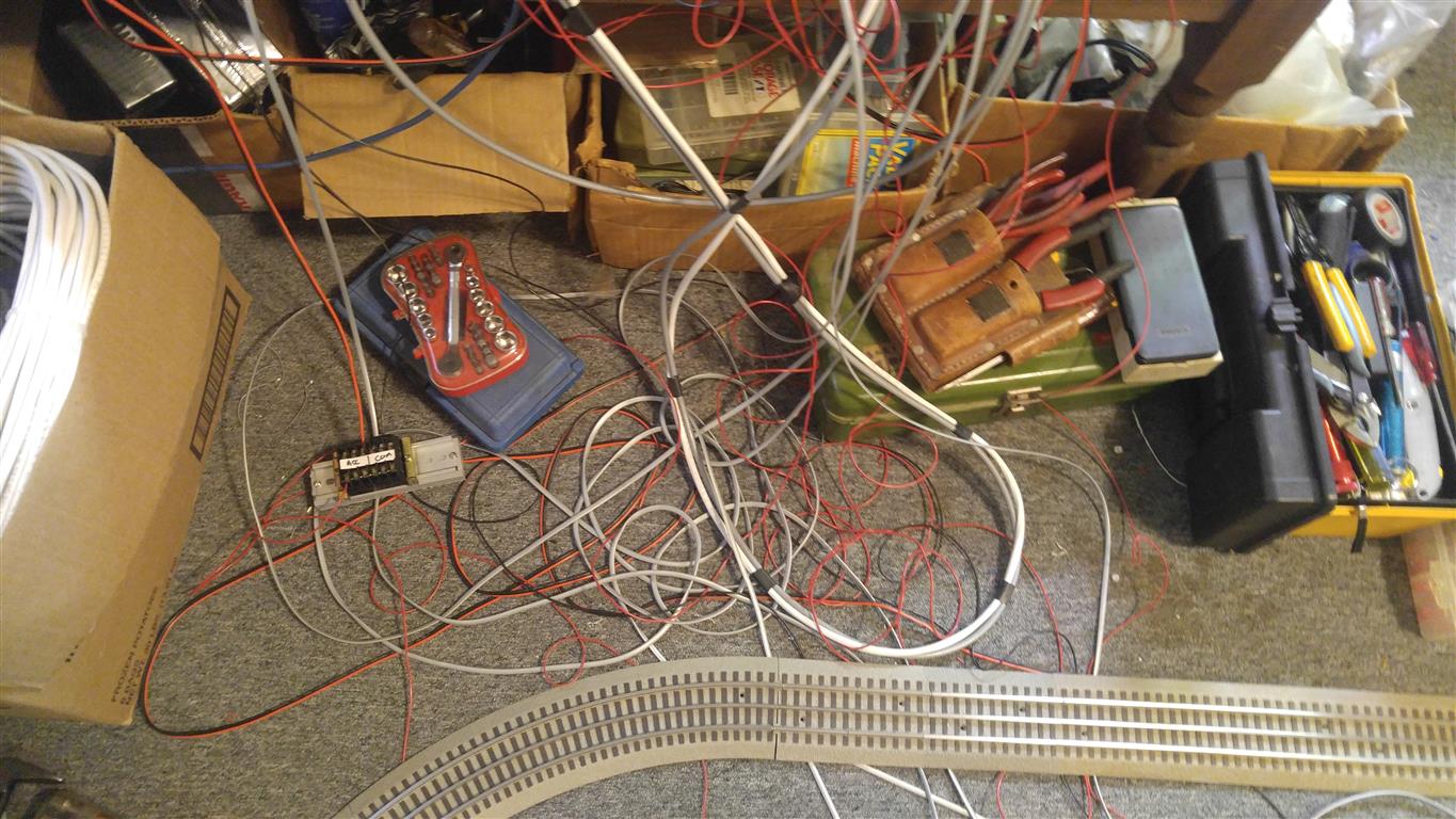
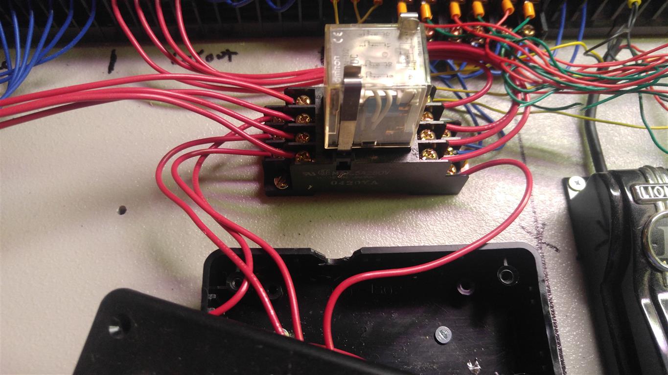
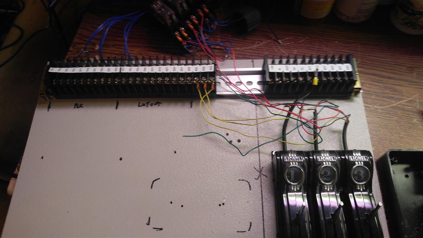
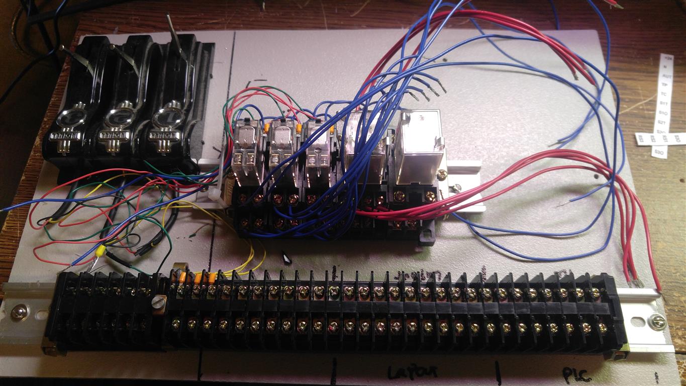
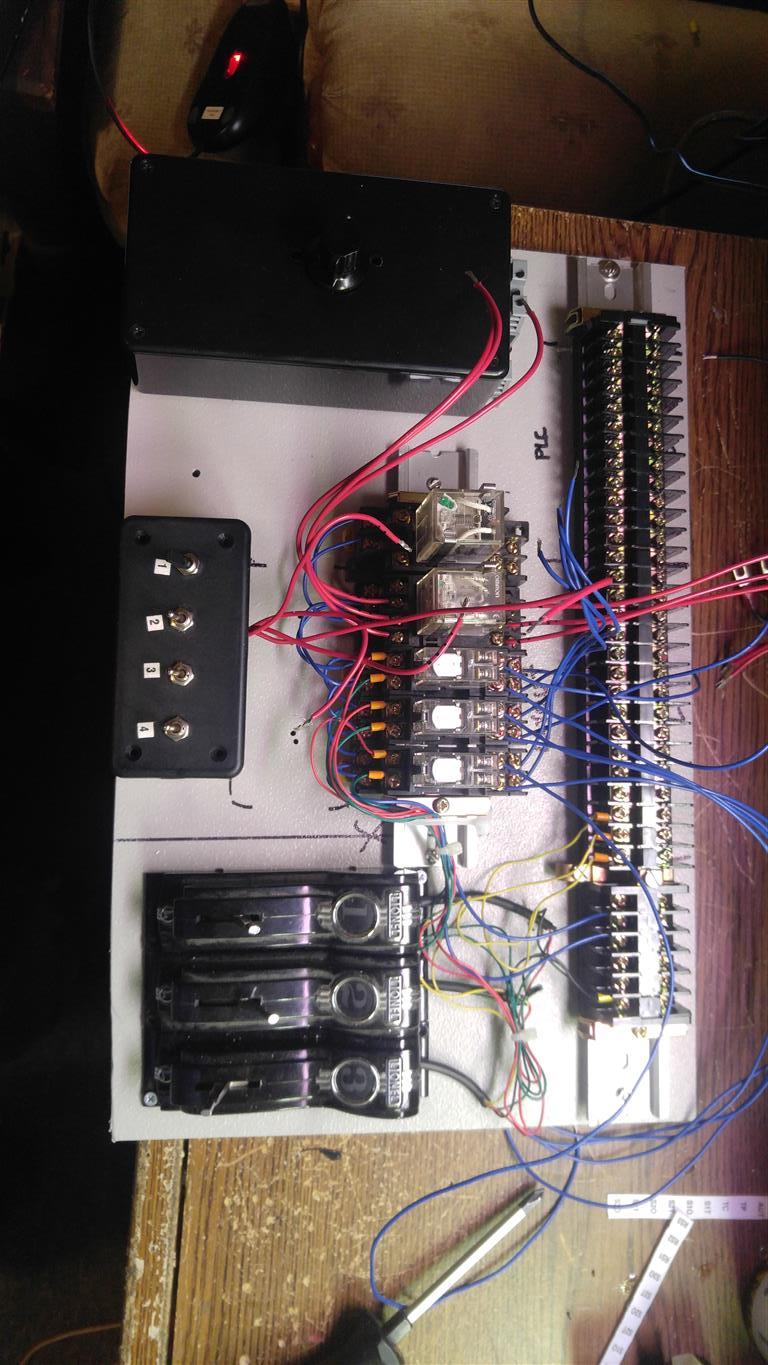
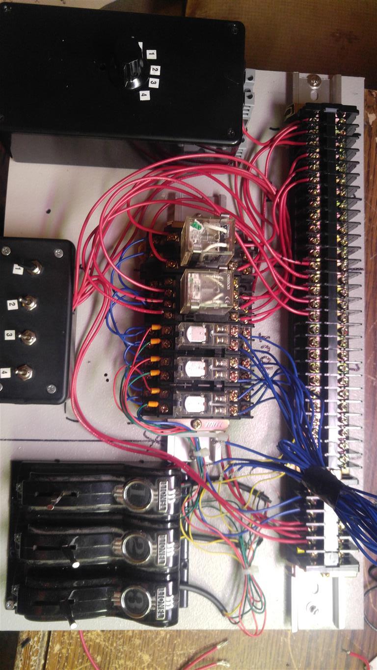
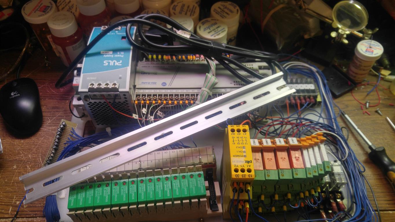
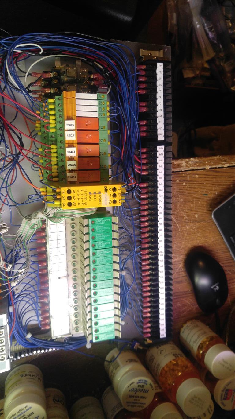
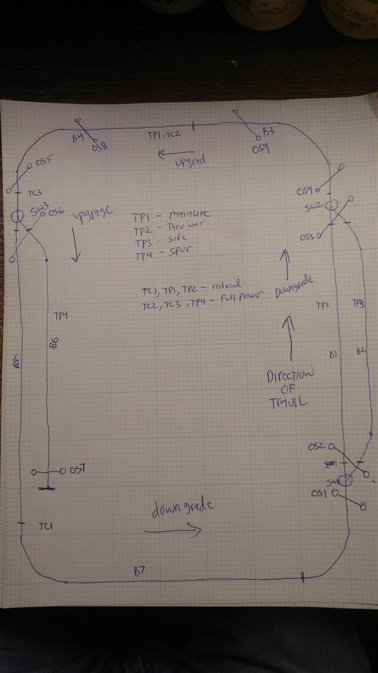
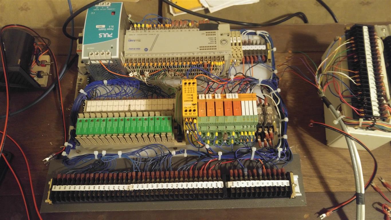
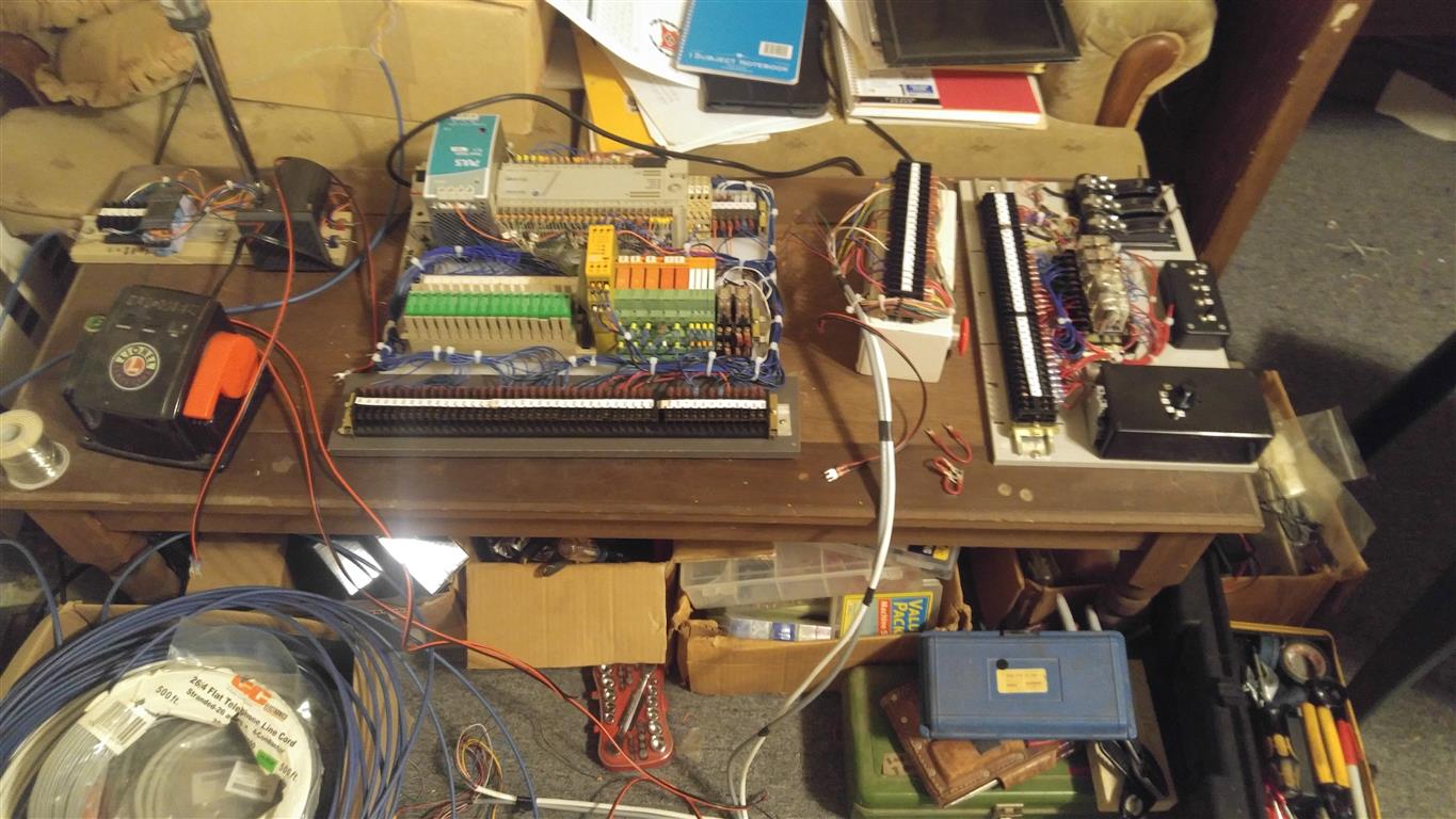
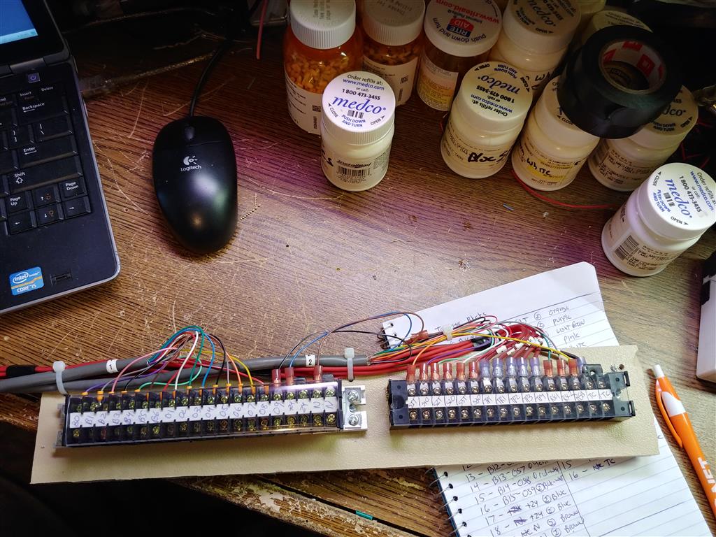
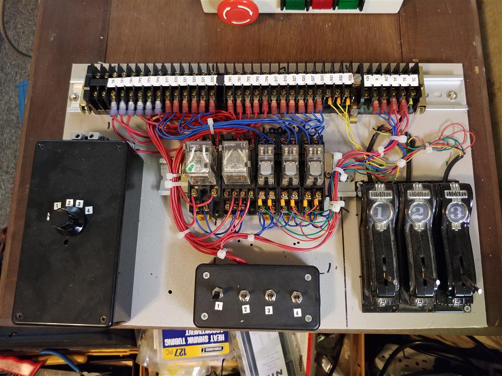
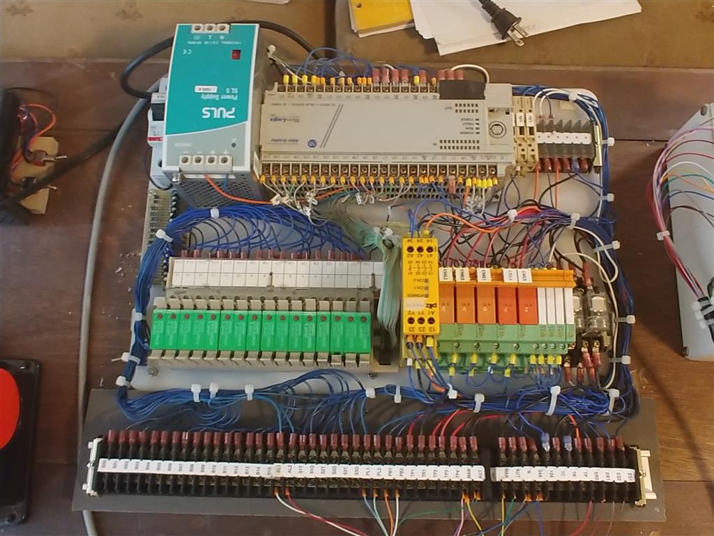
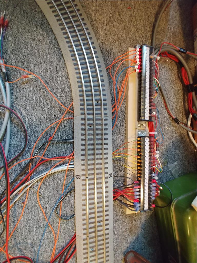
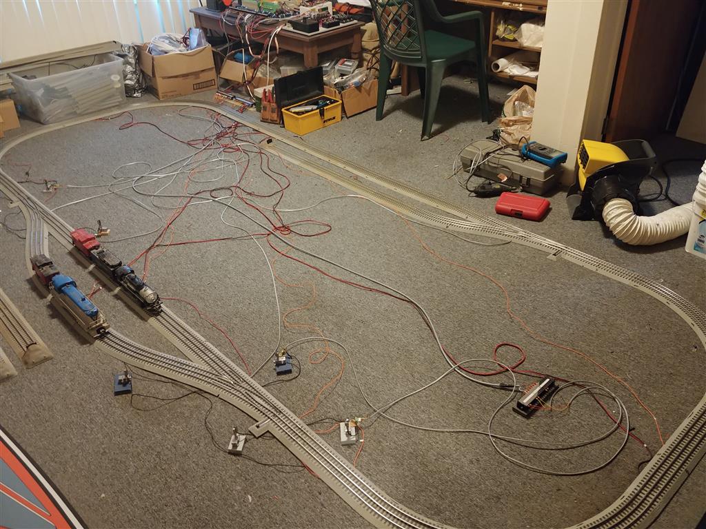
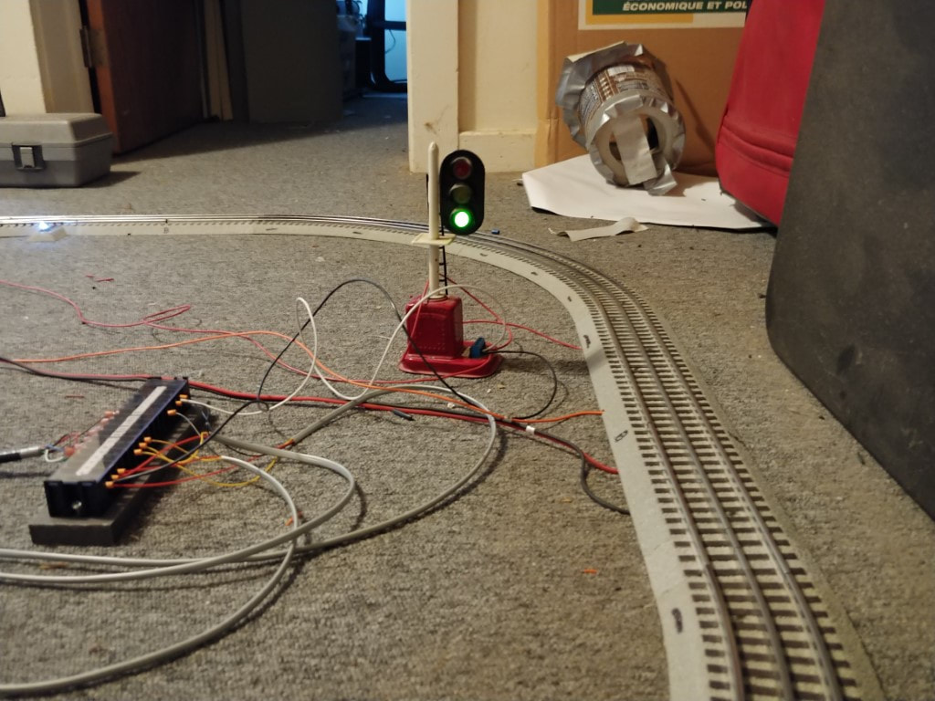
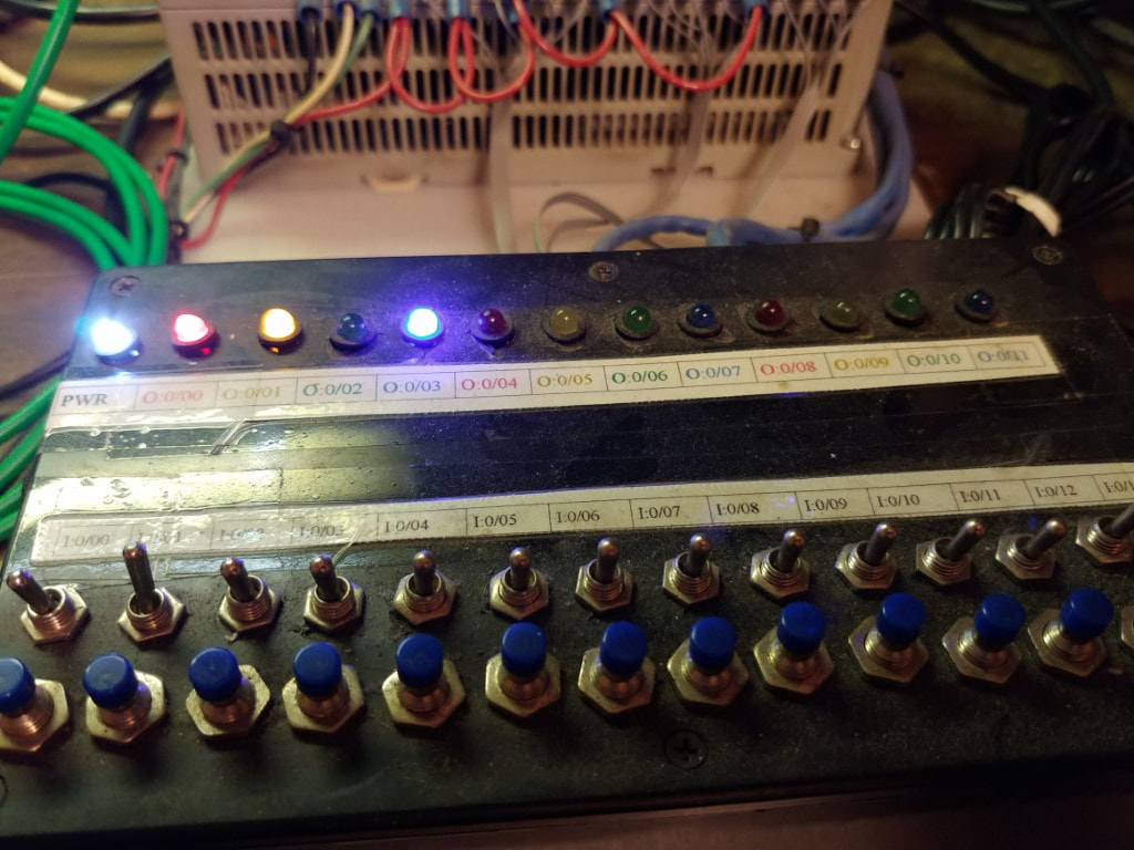
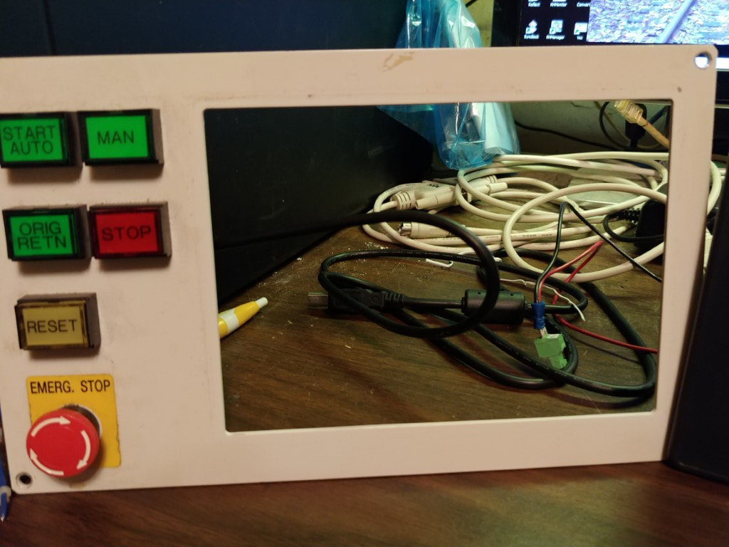
This long term project is to use a programmable logic controller (PLC) to control a model railroad layout. The parts obtained for this project was from former industrial equipment that was being scrapped and I was able to obtain parts from the machines. The project is not practical by normal means as computer and other controls already exist for model trains. The purpose for this project is to learn how to do programming on the PLC. The model railroad layout provides a "real world" example of controls compared to using a training kit which has buttons and switches for input, and simple LED lights for outputs. The electrical design for the project is based around the components obtained from the scrapped machines which is the only practical means to build this project without a high cost for the parts. Eventually the project will be used to control my layout that is around the wall of my room. This will include a HMI panel for control and input.
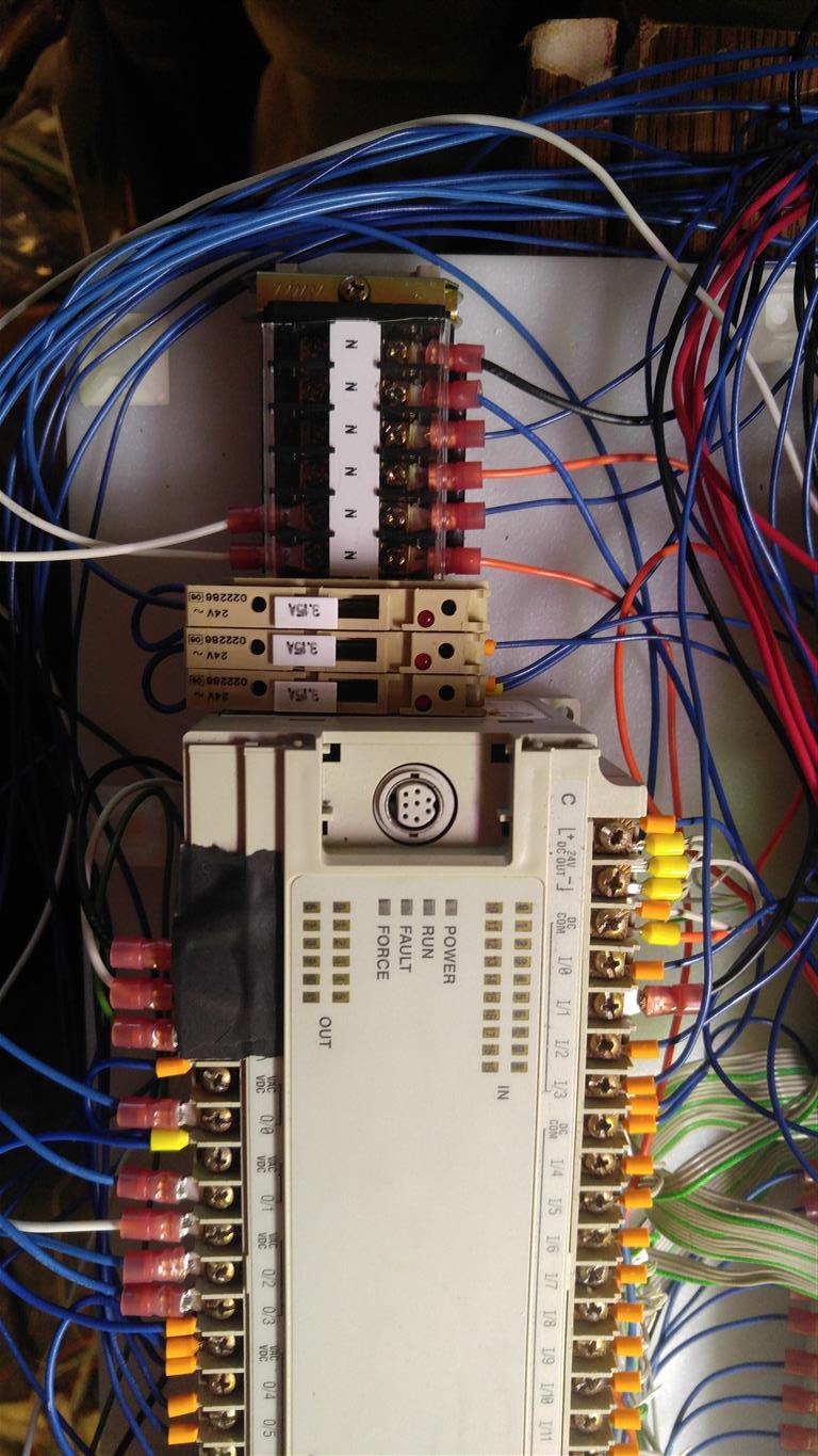
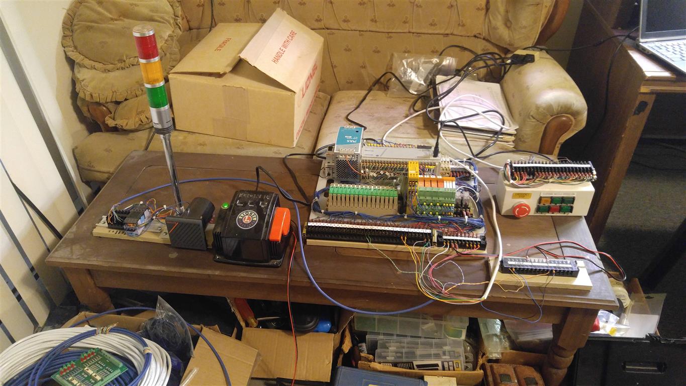
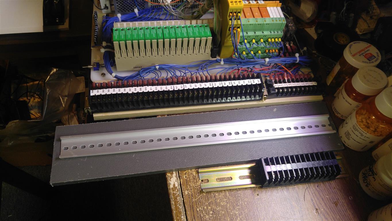
Since this PLC unit has no analog input or outputs, it is not possible to control the throttle or speed of the trains. I used a less expensive PLC module for this setup to start learning how to program. I have had some success with this setup but soon found limitations between the limited I/O and program space. I decided to upgrade to a newer and better PLC unit. The Second generation of that project is on its own page. I kept this page to show the initial development of the project and how it interfaces to the layout.
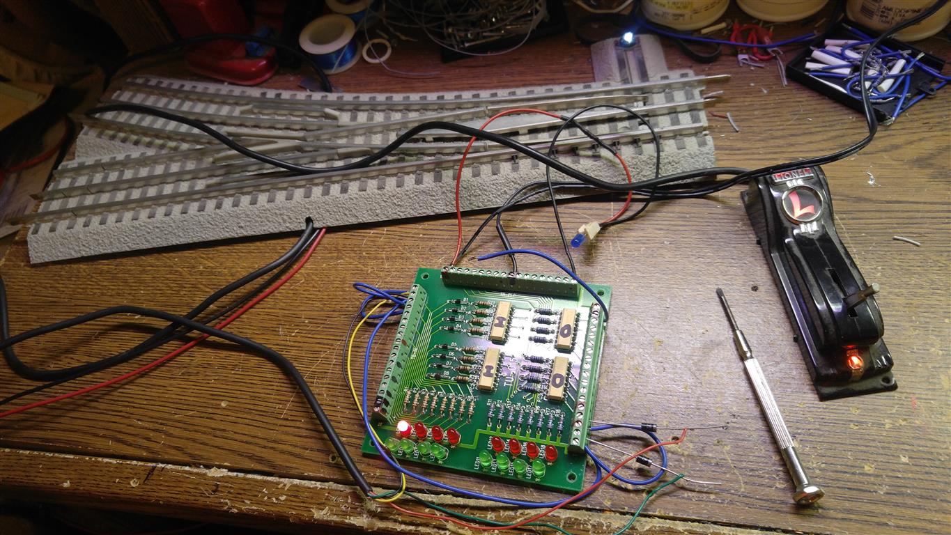
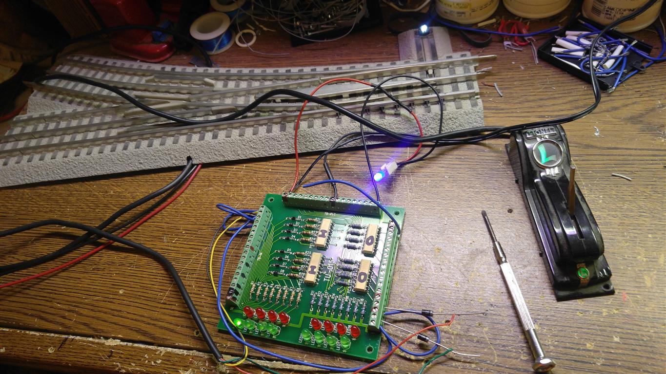


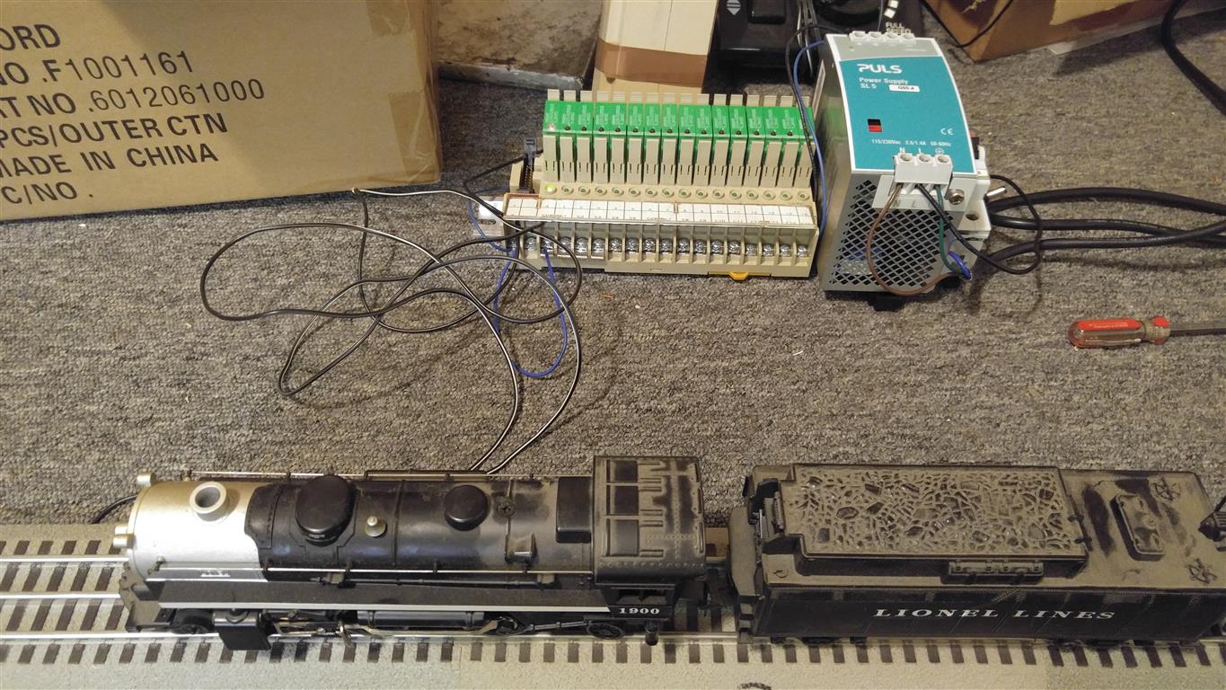
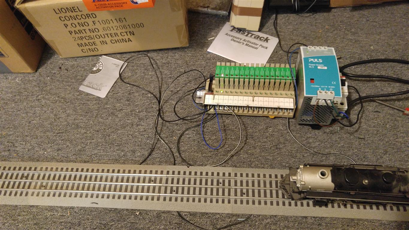


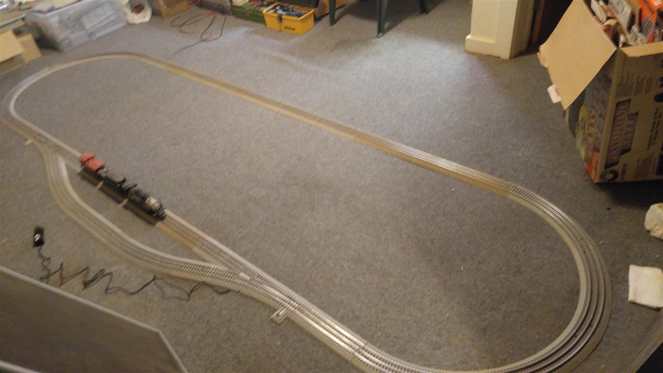
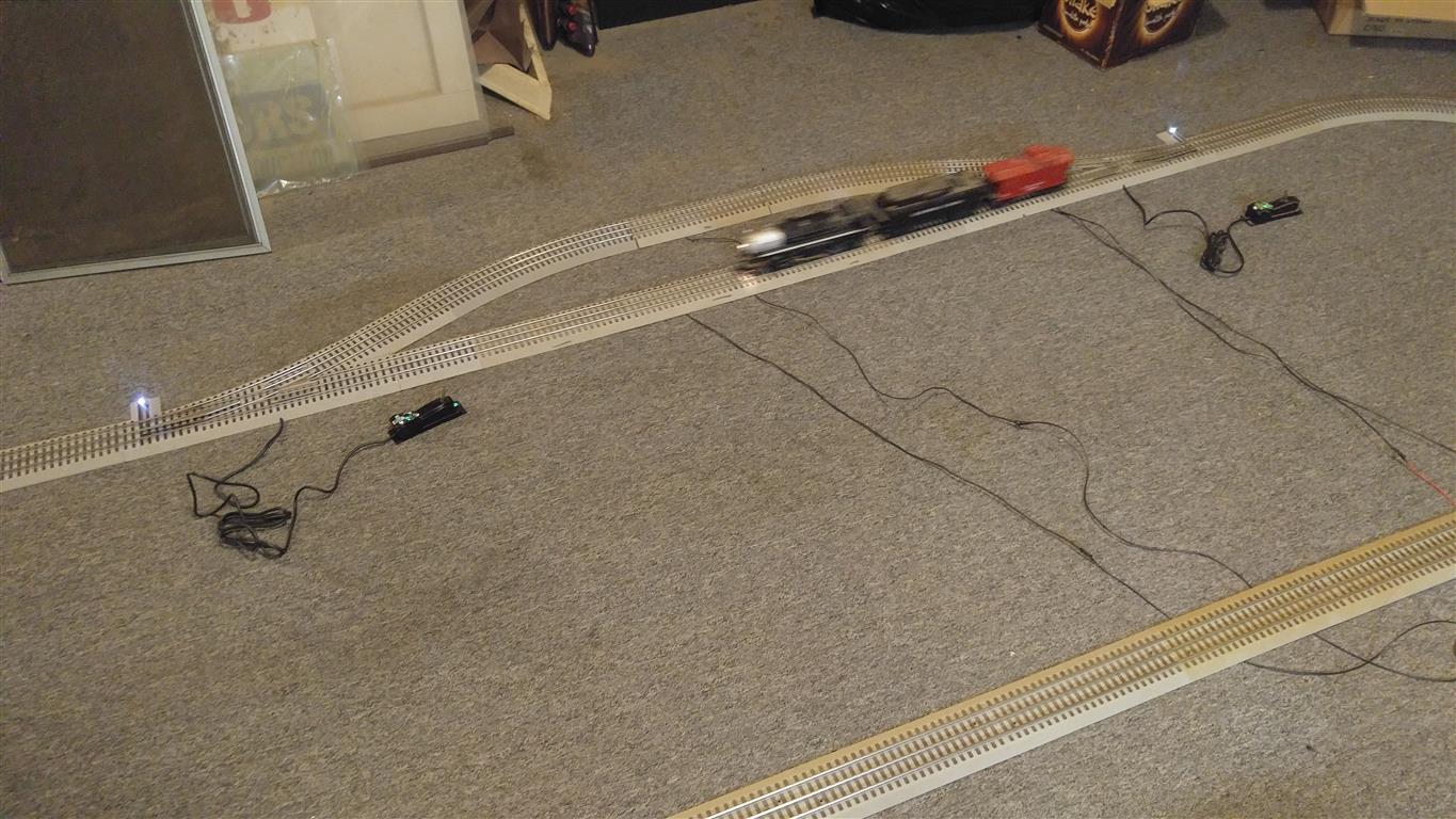


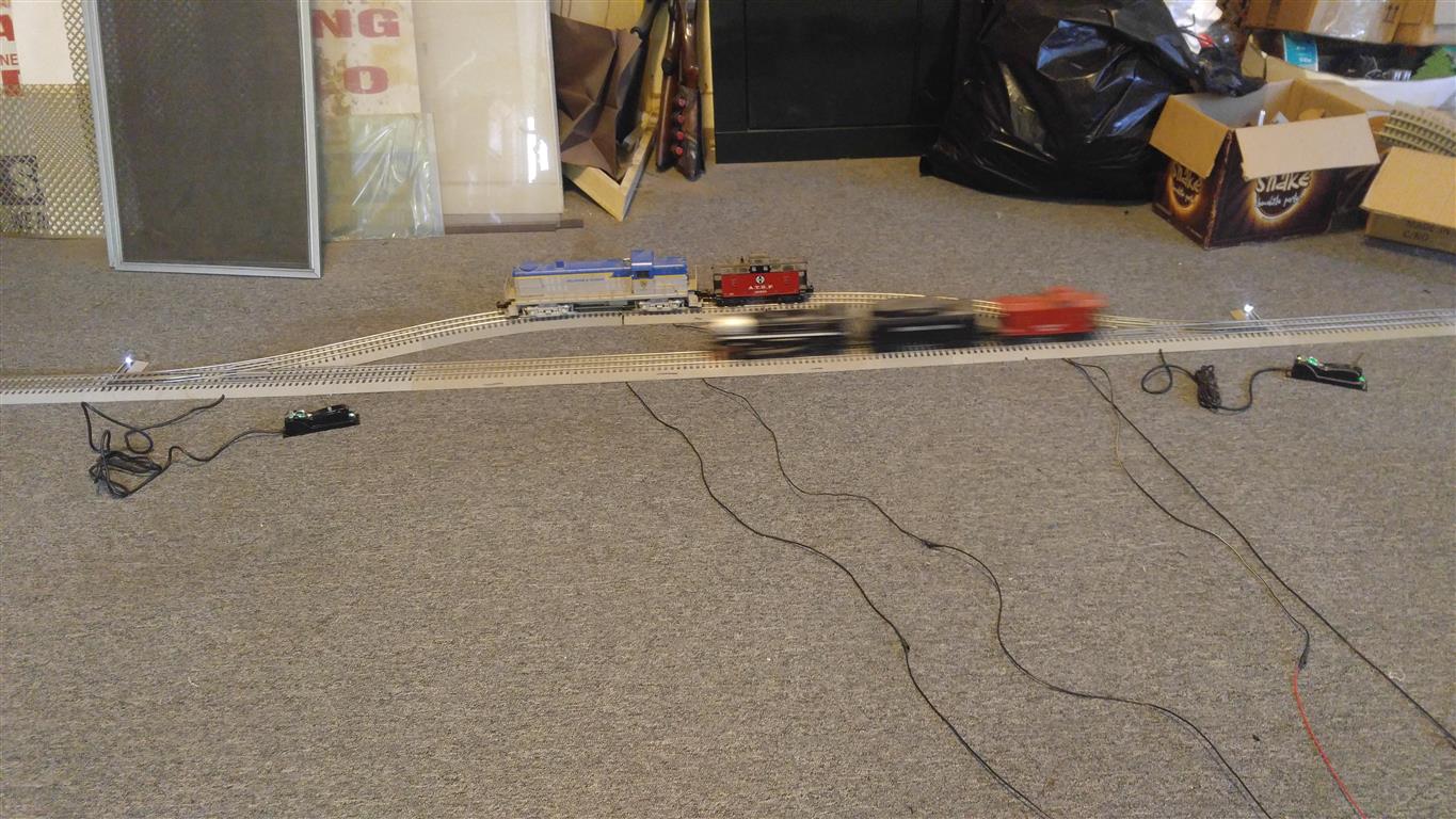
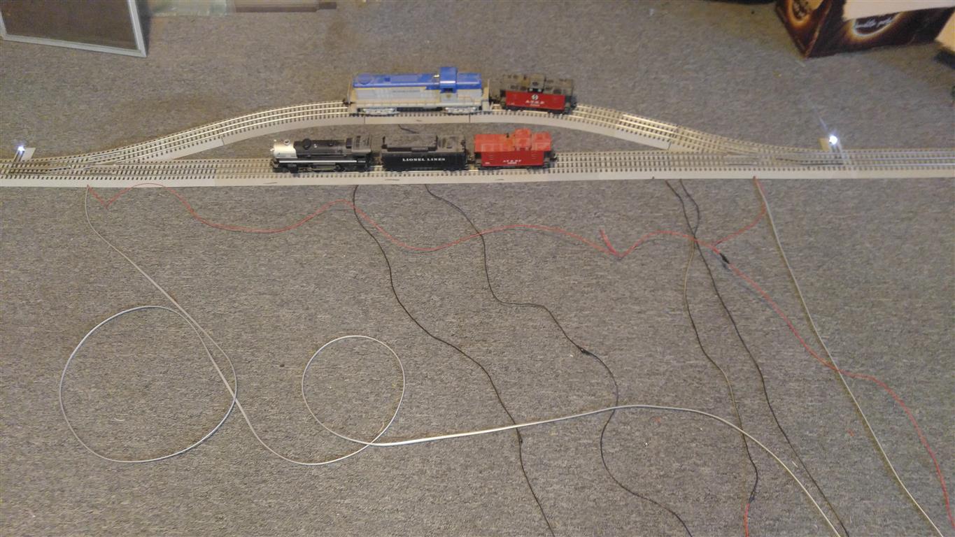


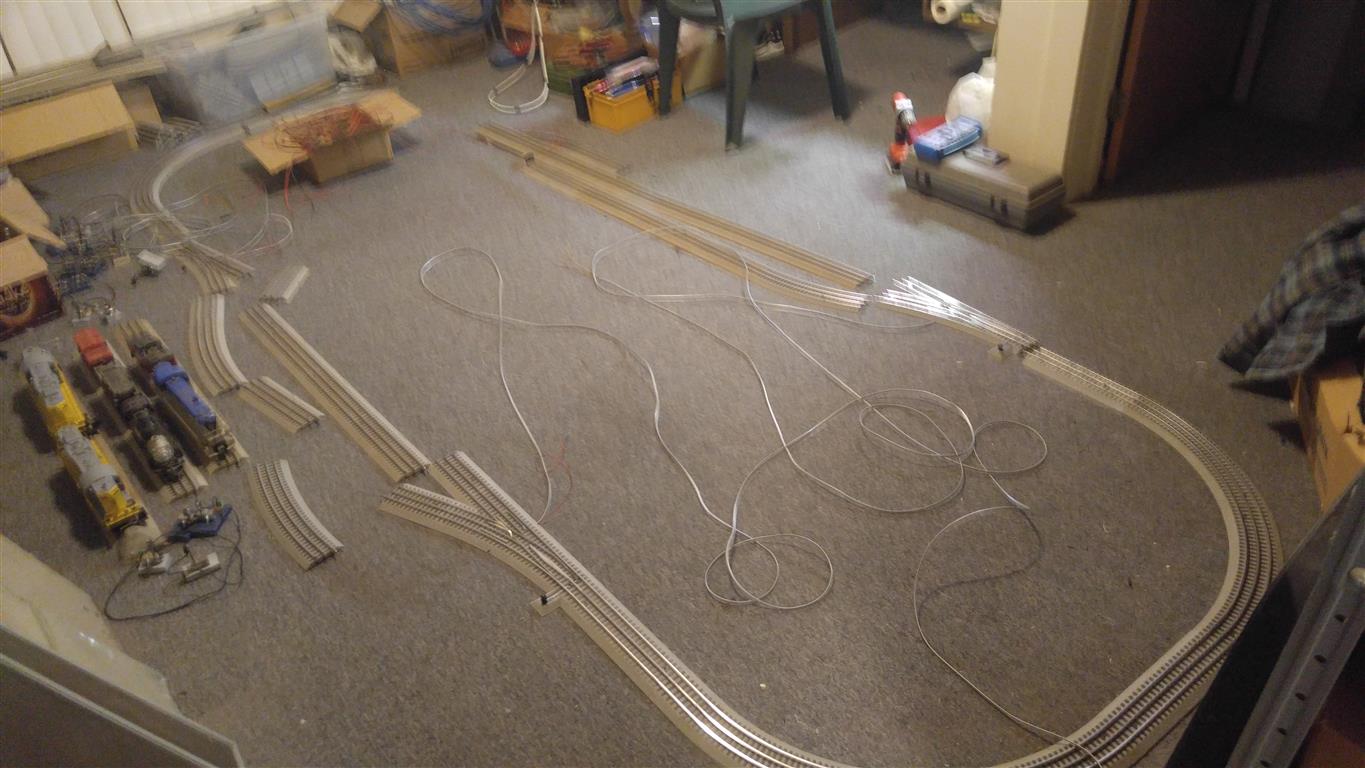


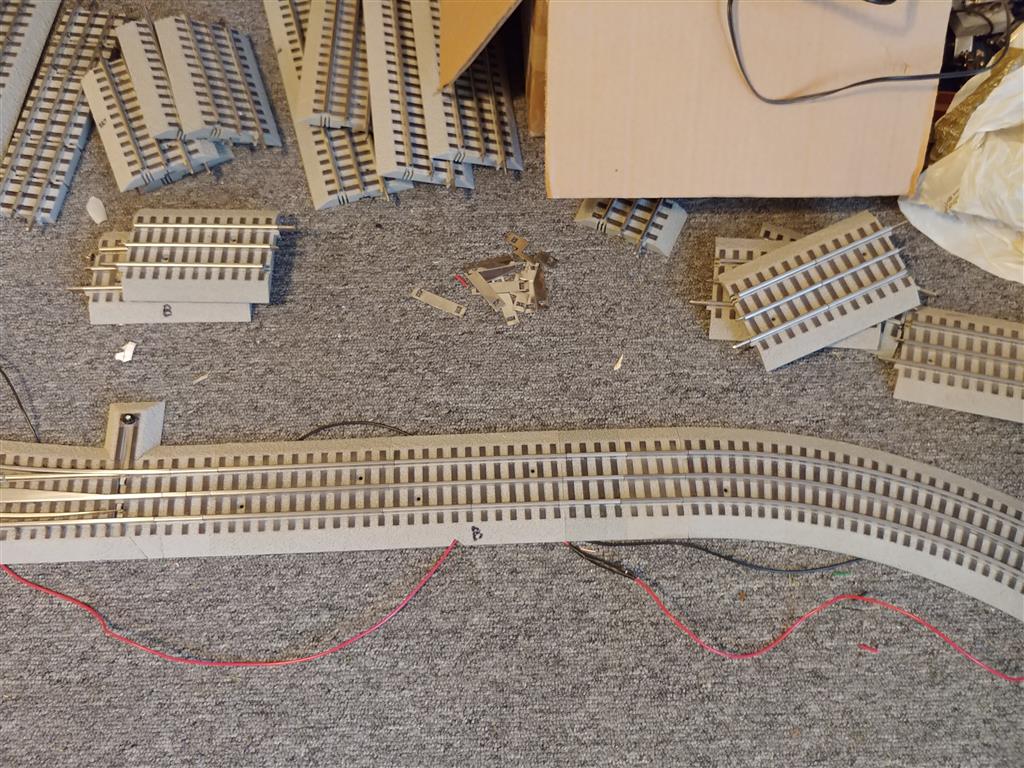
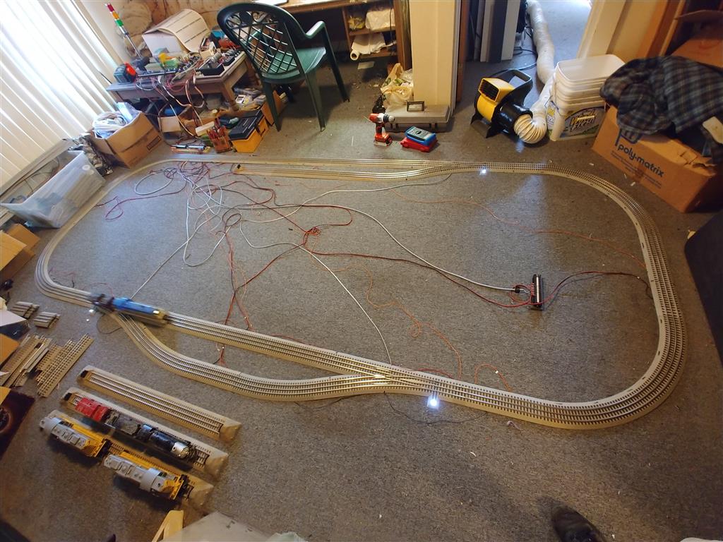
This is a series of videos of the first programs written with the test layout. The later pictures above were changes made to the layout so it would be a replica of my around the wall layout. Eventually I want this system to actually control my around the wall layout. For these first few programs I used just a few block detects and controls to start the learning process. Once these were done, I changed it to be a replica of my wall layout.
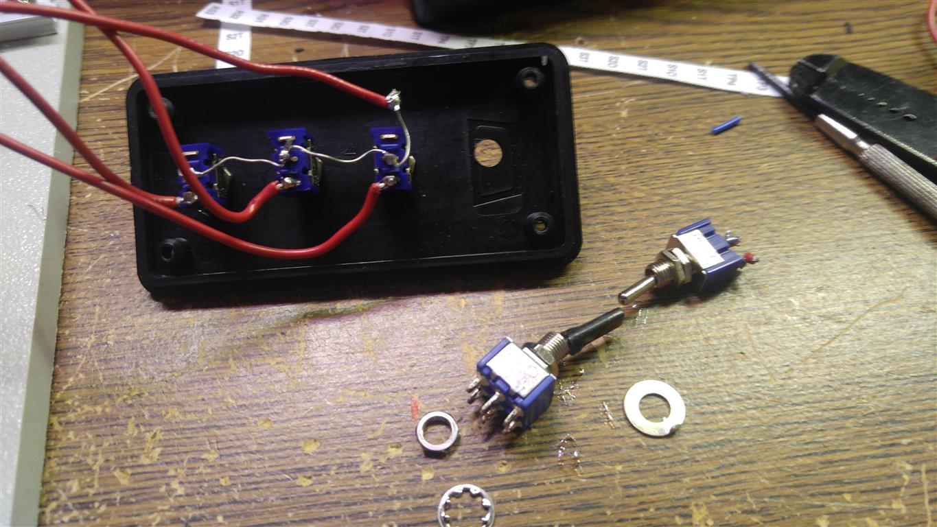
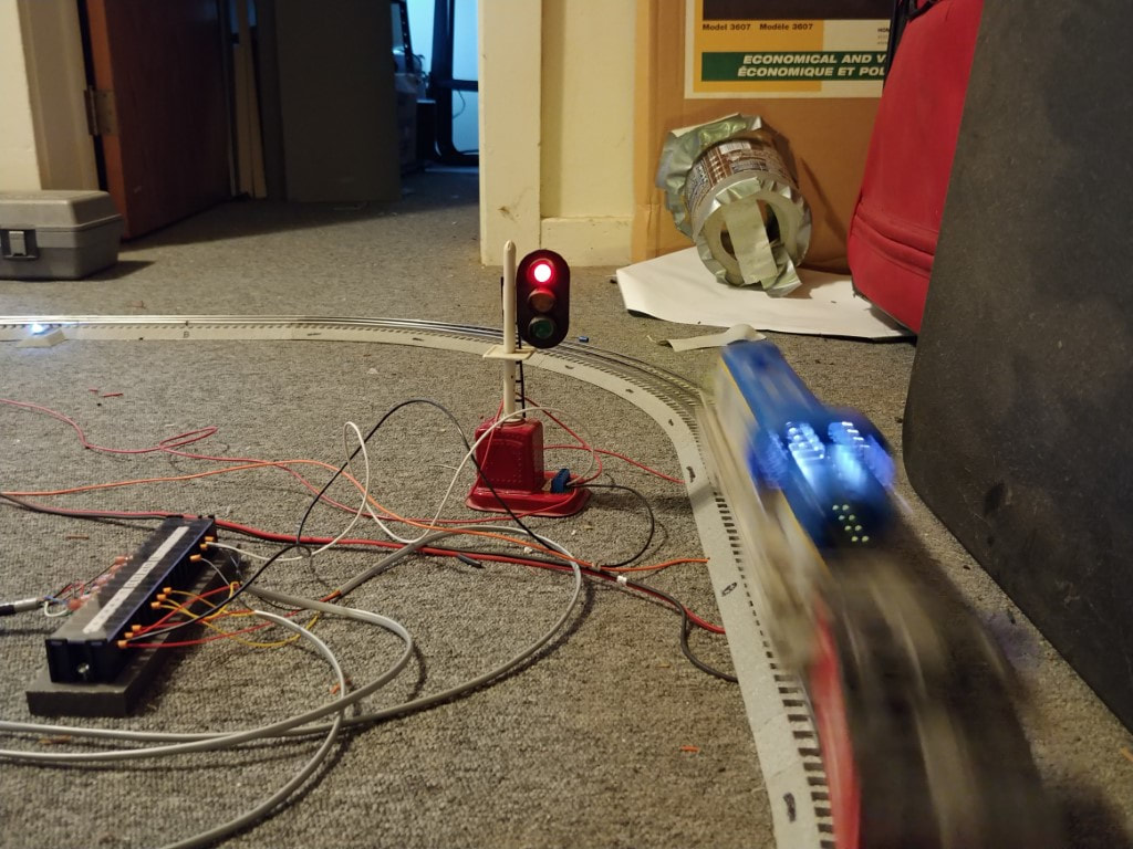
For the first few programs, I locked the locomotives in forward only. Normally Lionel trains can run forward or reverse, but for the first few programs, they will only move forward.
For the first few programs, I locked the locomotives in forward only. Normally Lionel trains can run forward or reverse, but for the first few programs, they will only move forward.
First program written
Derailed train test
This program changes the train in a different sequence, but it kept messing up with the last steps.
Interchanging the locomotives, the program works.
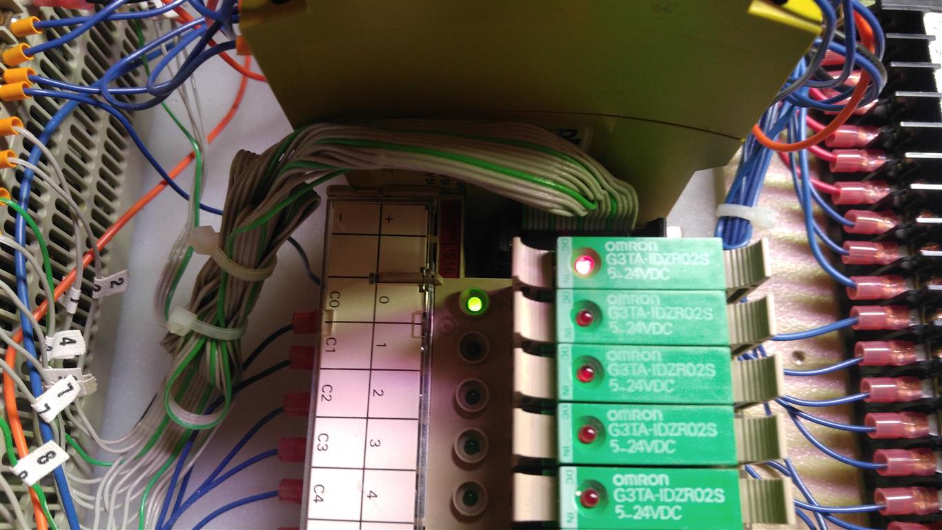
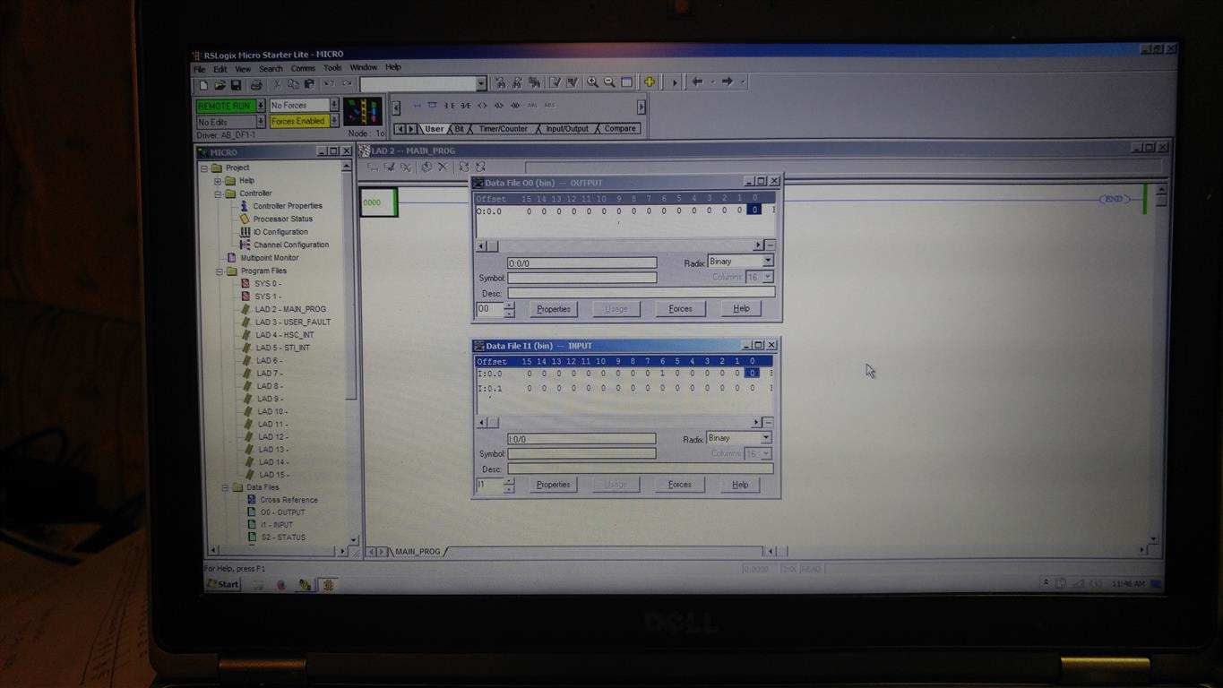
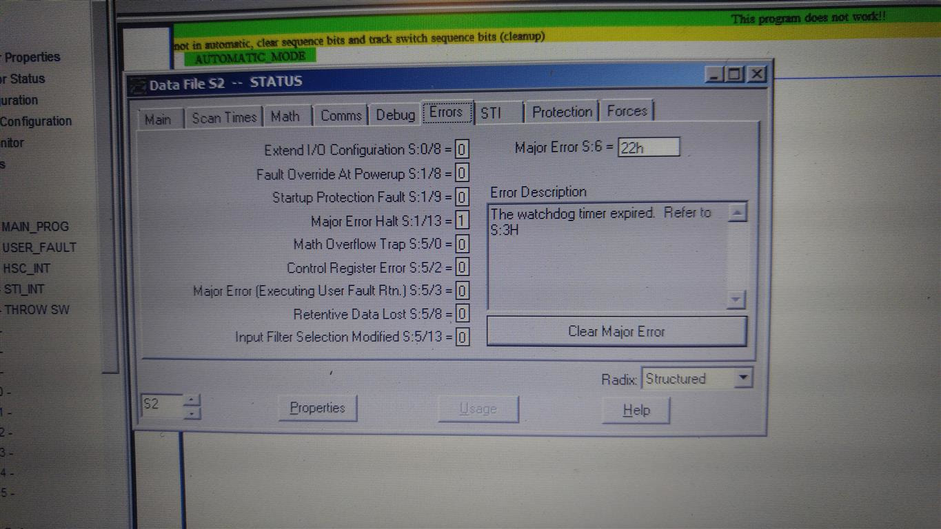
Watching the inputs on the PLC unit, the problem is clearly seen at 0:23 - 0:26 seconds.
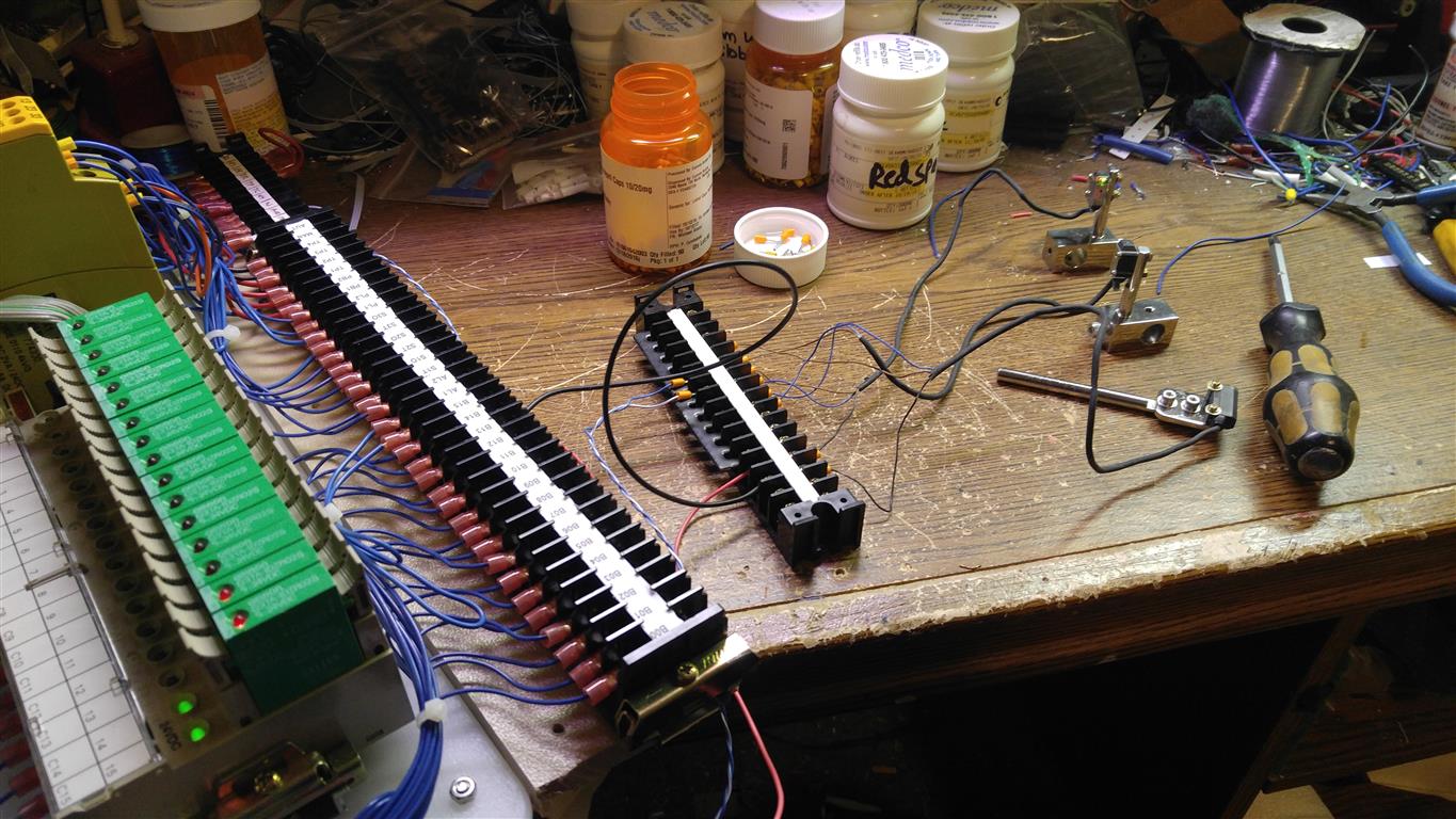
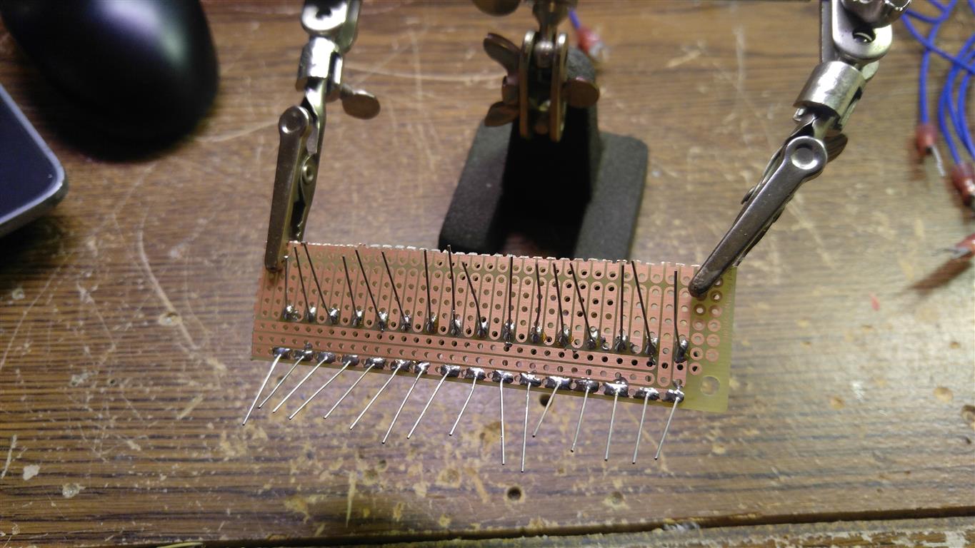
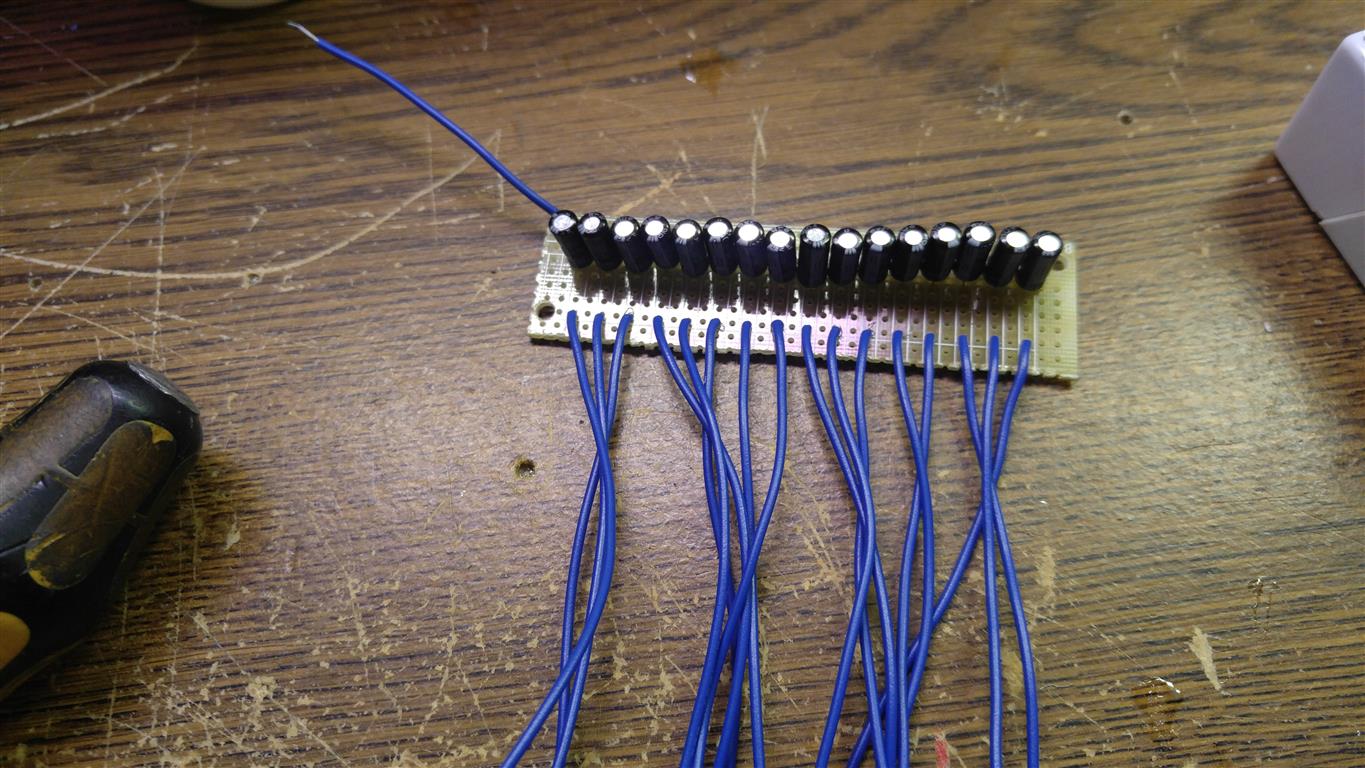
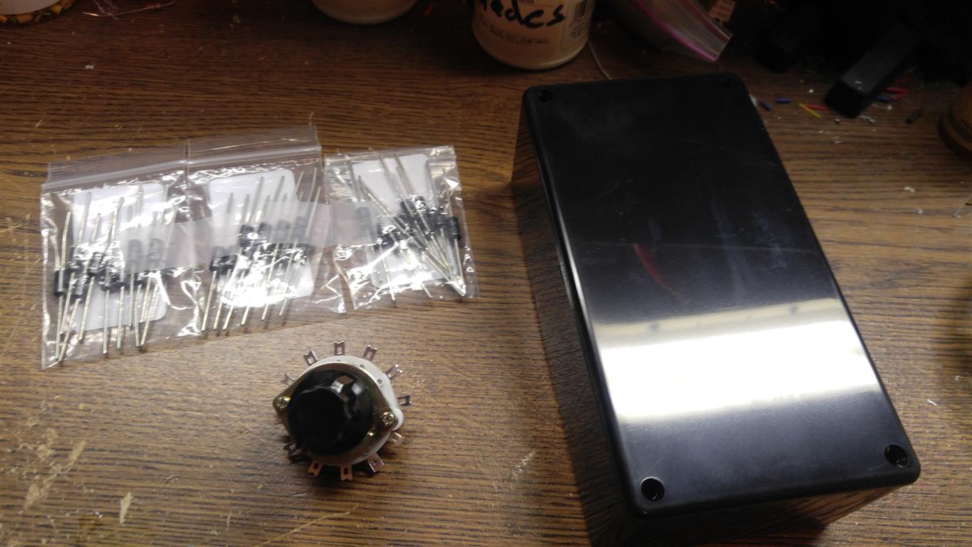
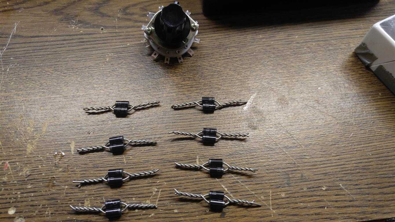
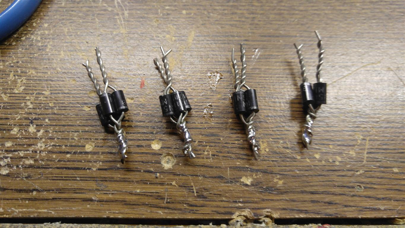
Adding capacitors to the input block to eliminate the chatter. Running the program with the trains in position that originally caused the problem shows it is works.
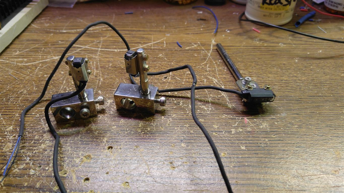
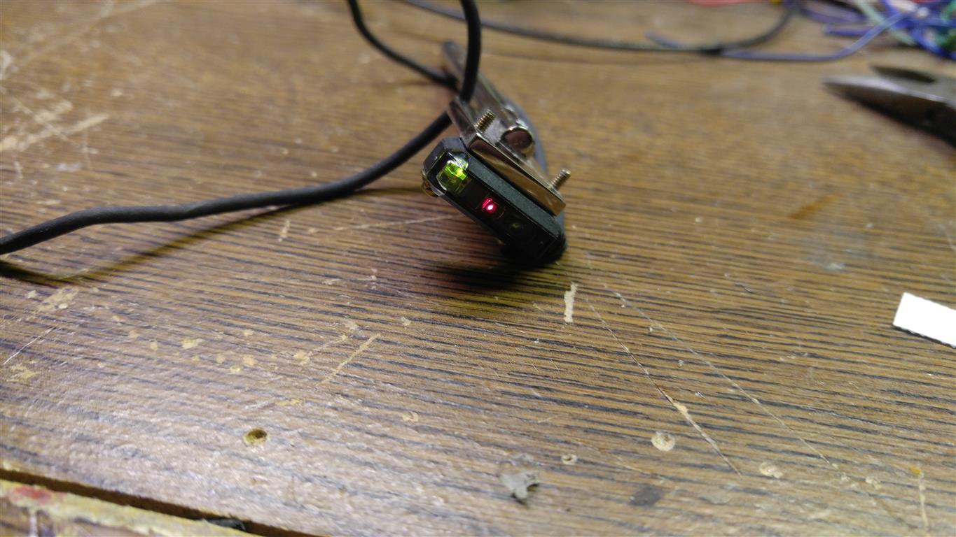
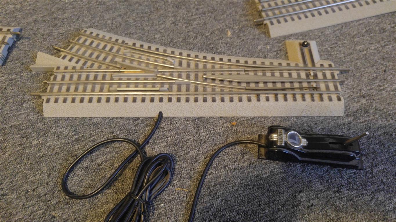
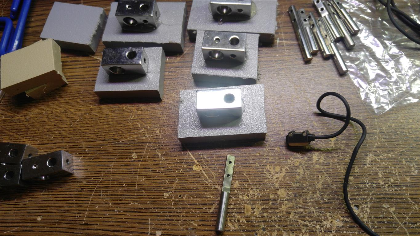
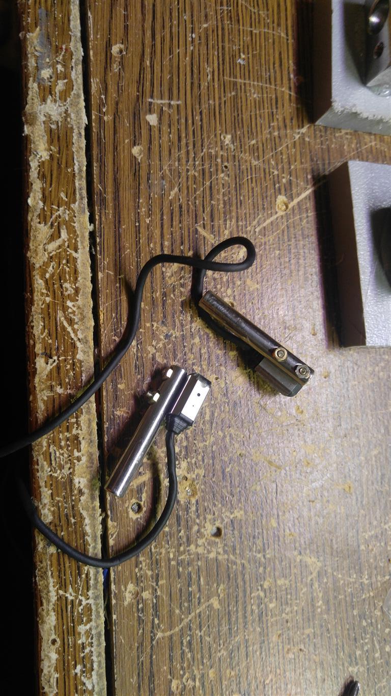
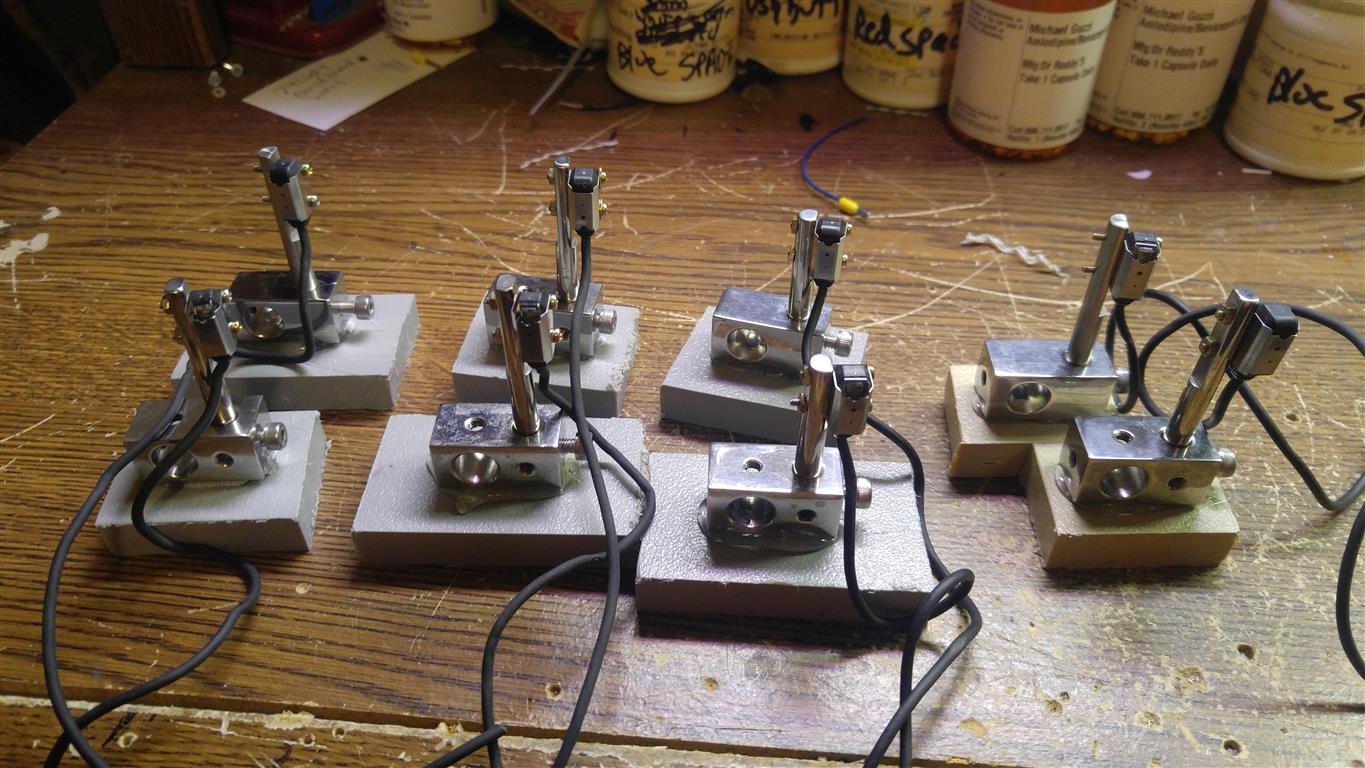
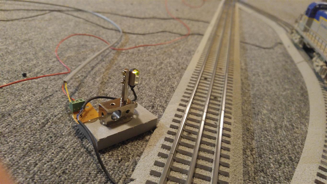
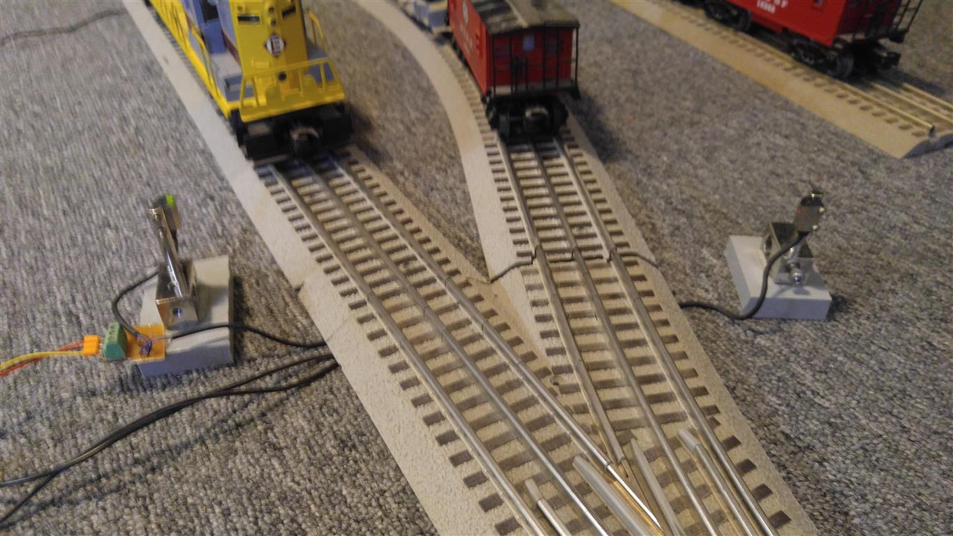
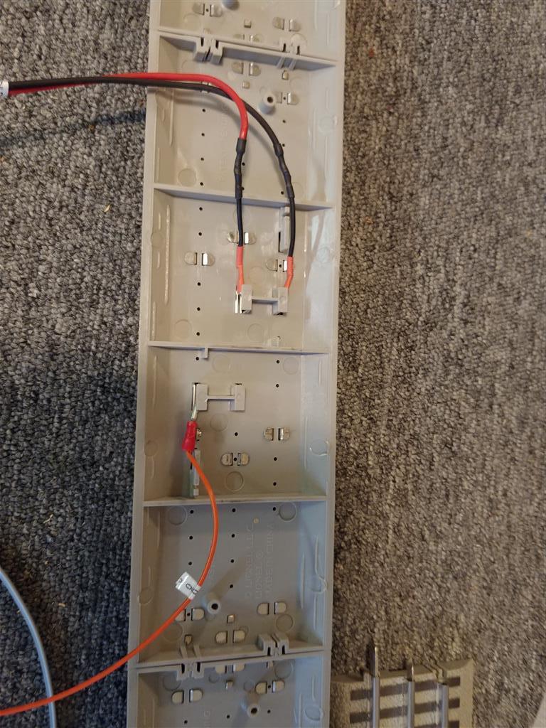
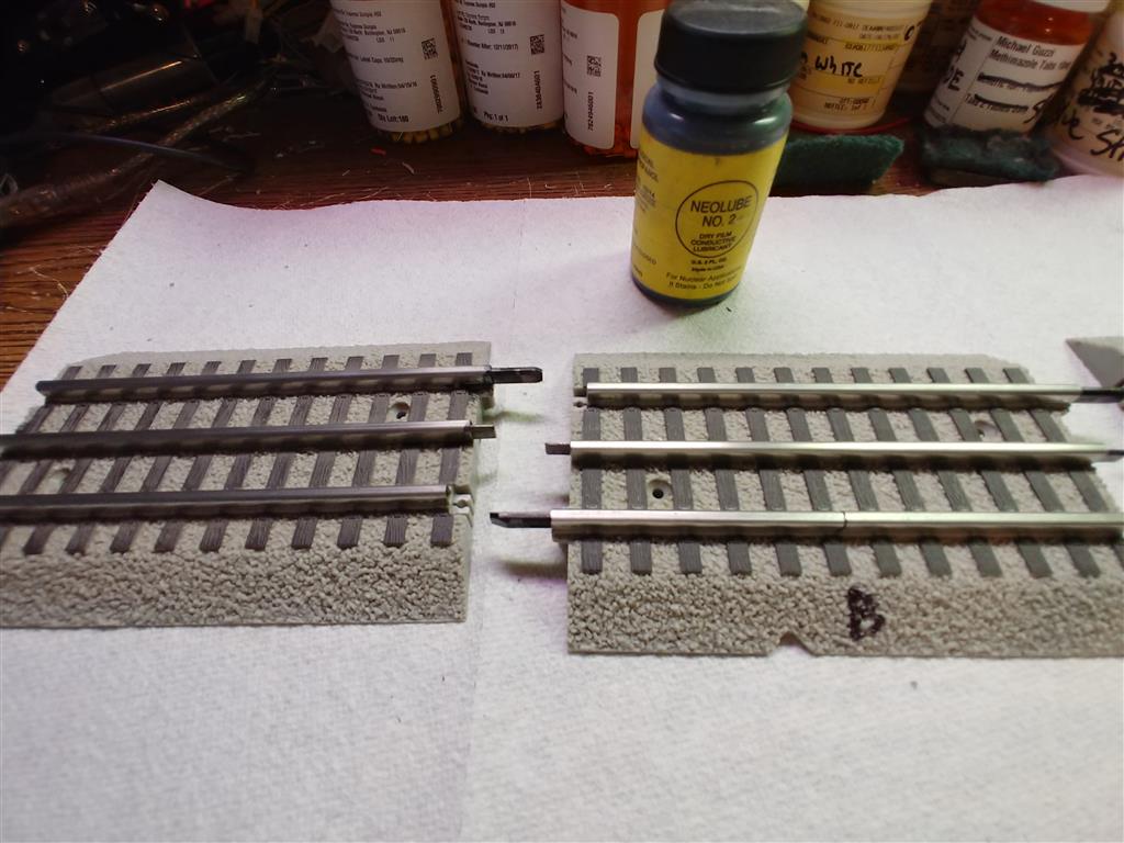
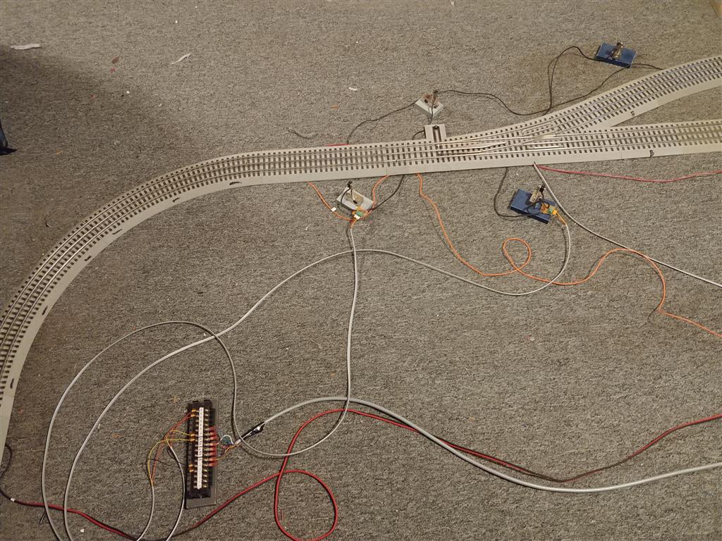
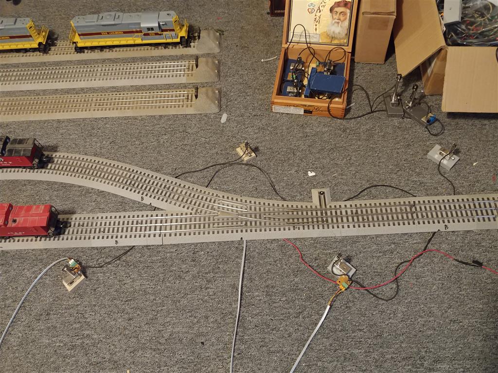
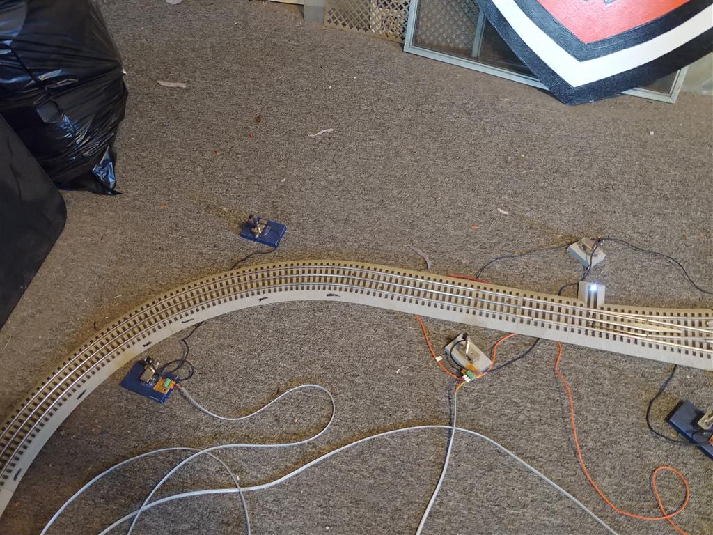
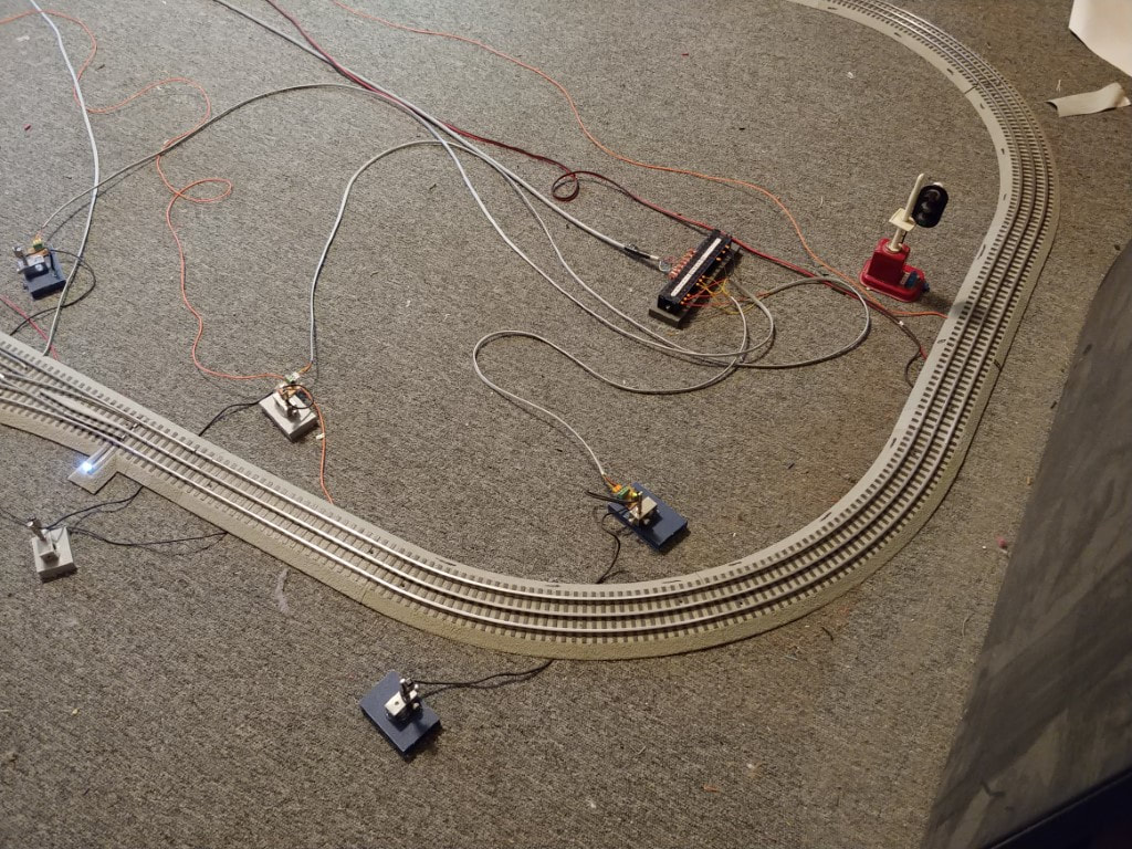
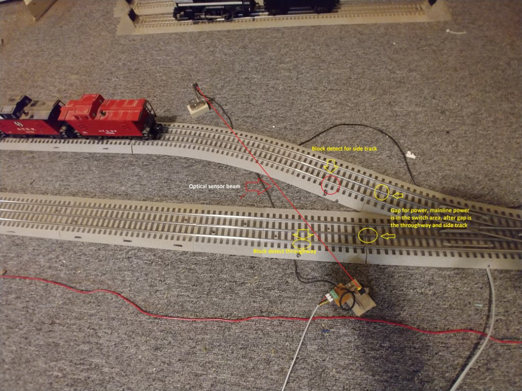
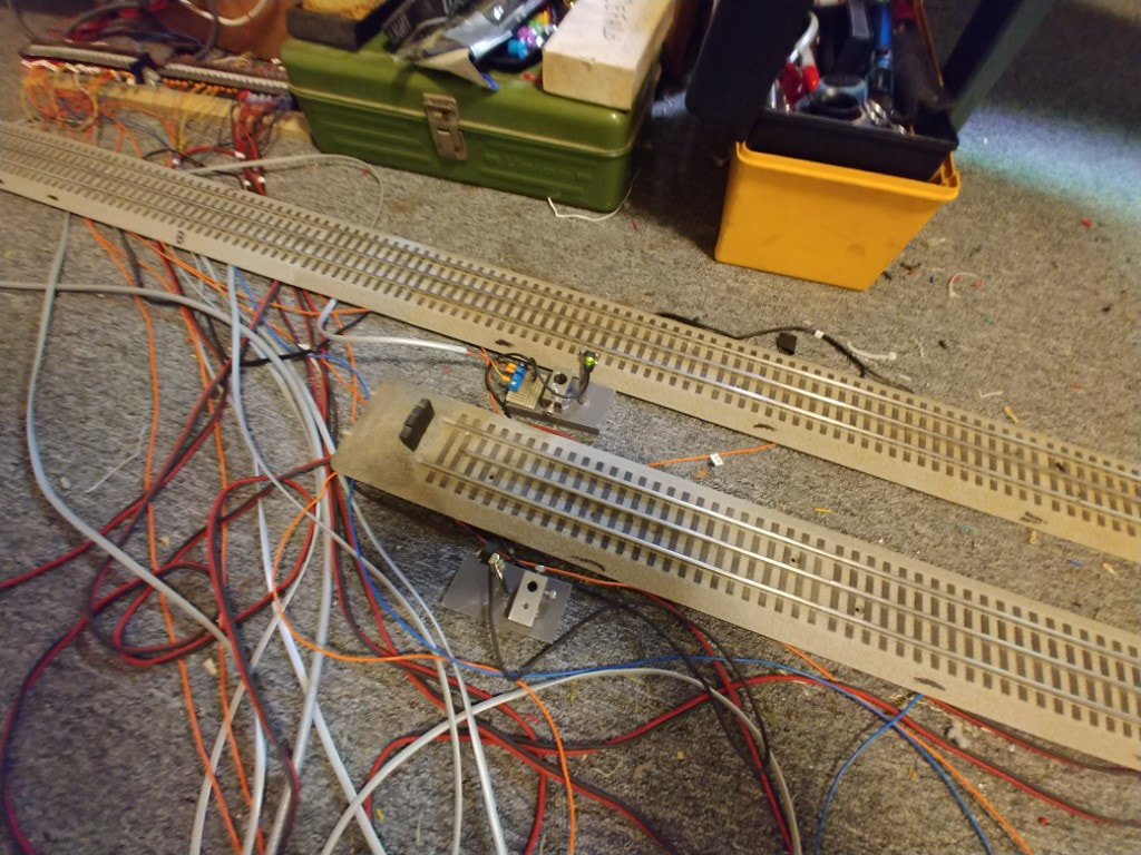
The next step was to add optical beam sensors across the switch area. This way if the train is in the switch area the program will not change the switches and instead throw an alarm. Test shown here.
Forward and reverse tests
With the optical sensors in place now, the capability to sense the direction of the train can be done. This is the first program test with the locomotive set to normal run, meaning it can run forward or reverse which is the normal setting for these trains. Lionel trains sequence with the momentary drop of track power. The sequence is:
Forward - Neutral - Reverse - Neutral, then continues to forward next.
However each train can act different. Some models will revert back to forward if the track power is off for more then 20 seconds. Others will stay in the sequence and continue with the next sequence no matter how long track power is off. This means holding a variable in the PLC memory to indicate what the next sequence will be when track power is applied cannot be done. Therefore the PLC has to sense the train direction and cycle the track power several times to insure the train moves in the desired direction. This becomes important with the spur track since the train has to back put of the spur to the main line then sequence to run forward once the switch is thrown back to the throughway. The following three videos is the first test of a forward and reverse program.
First test is to have the train move forward
Second test is to have the train go in reverse.
Third test is if the train does not move
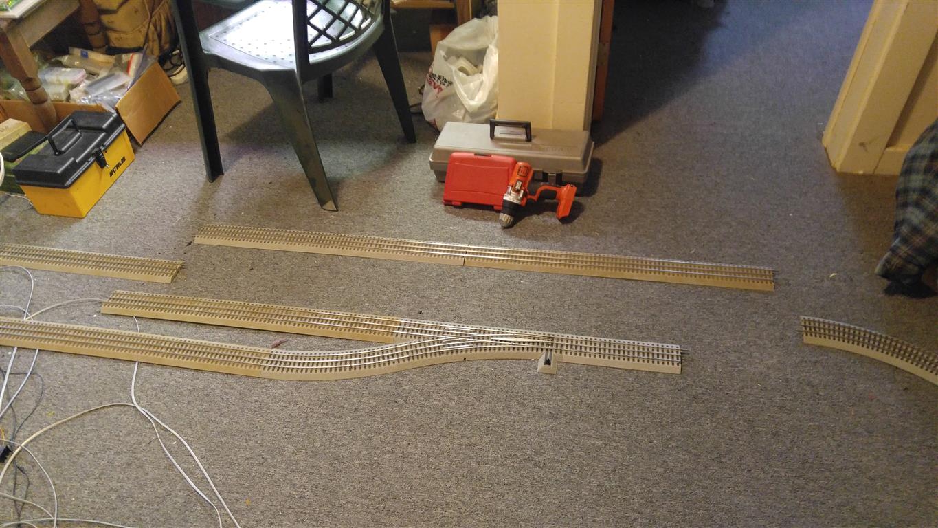
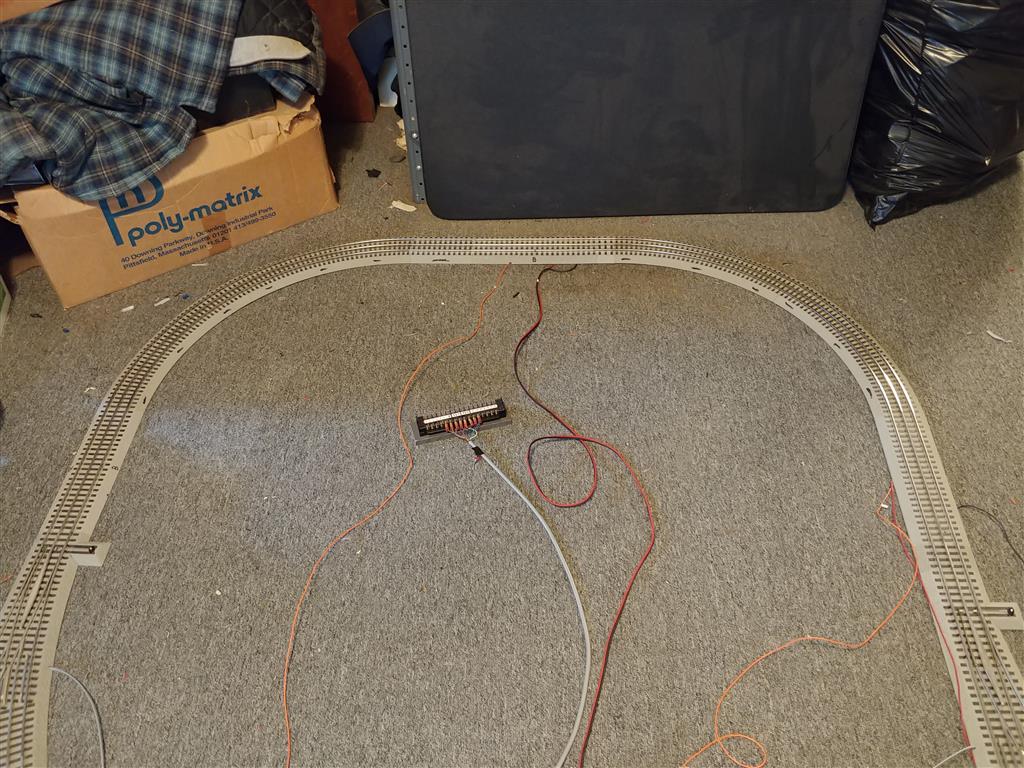
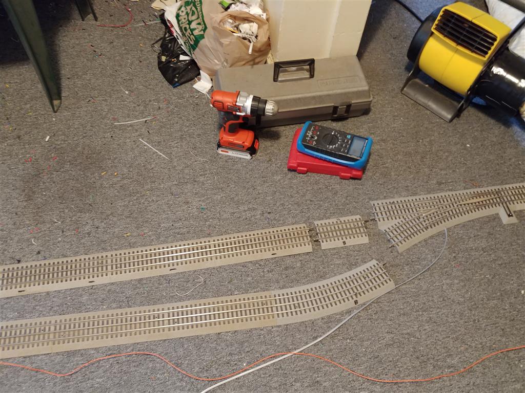
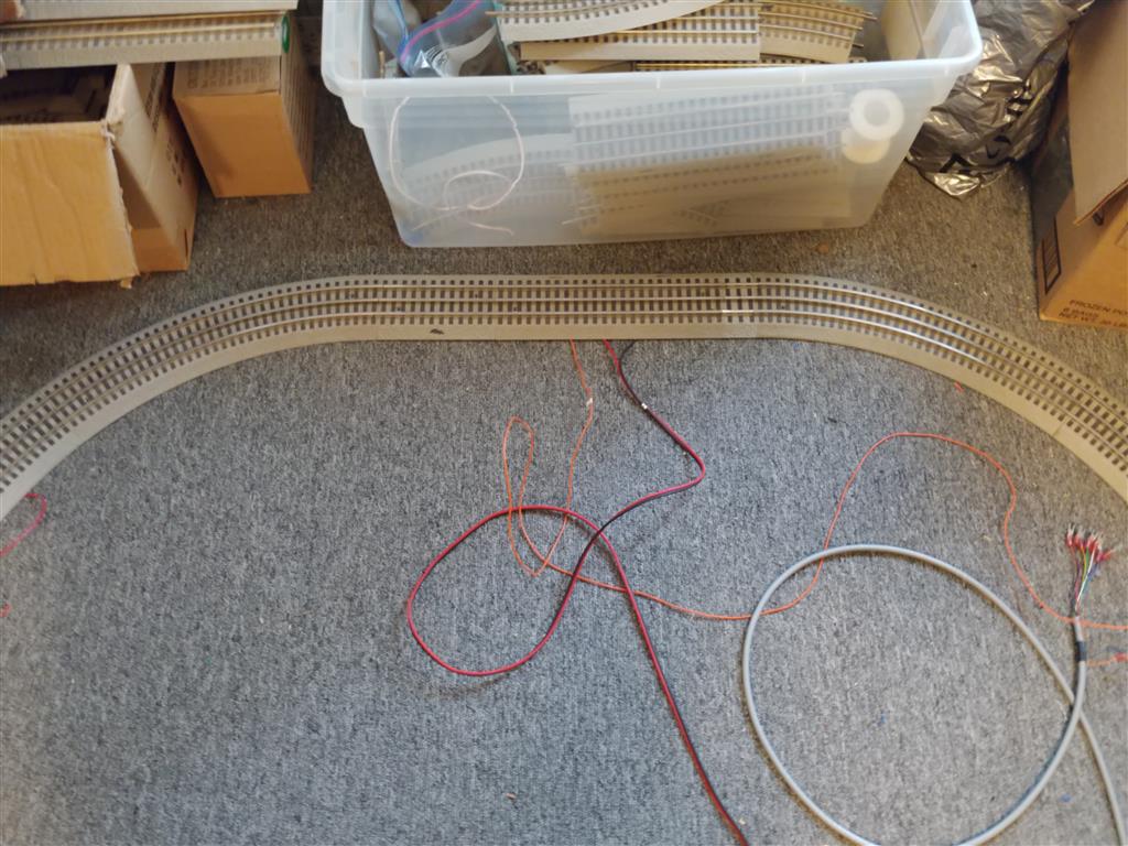
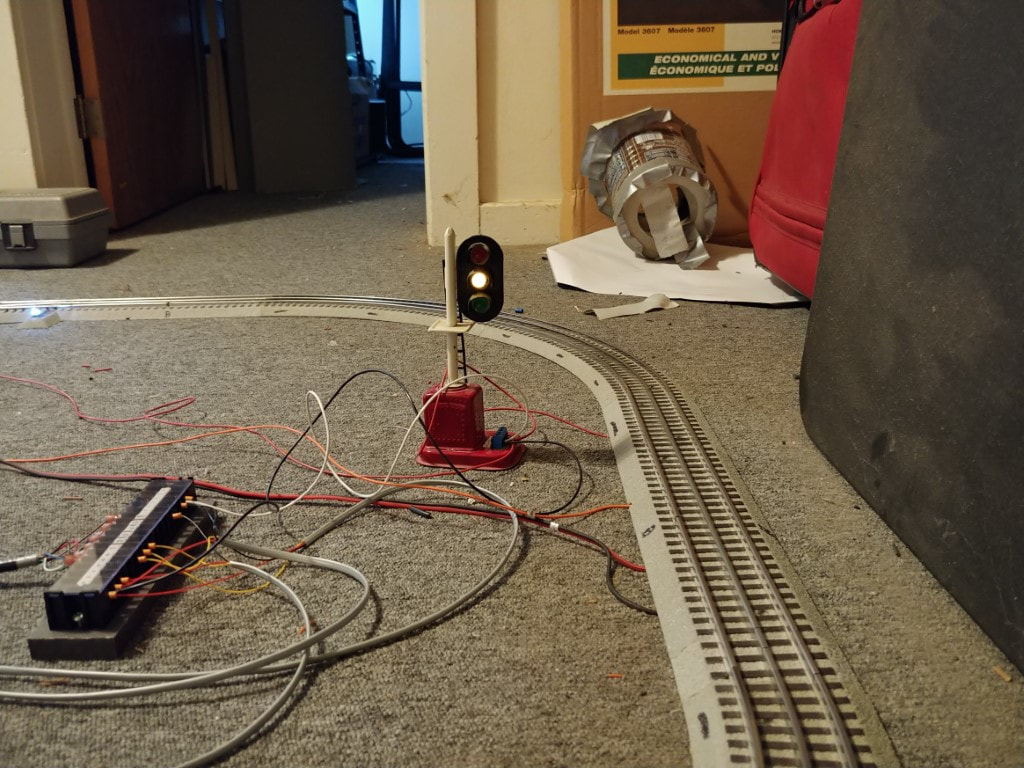
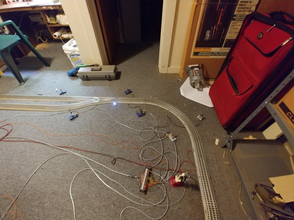
Rebuilding the layout to be a replica of the wall layout.


Forward - Reverse code with new layout test
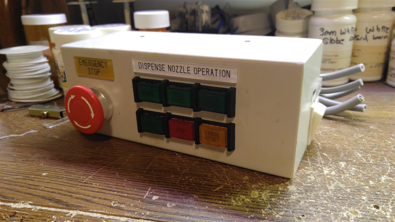
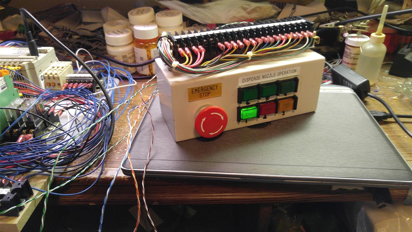
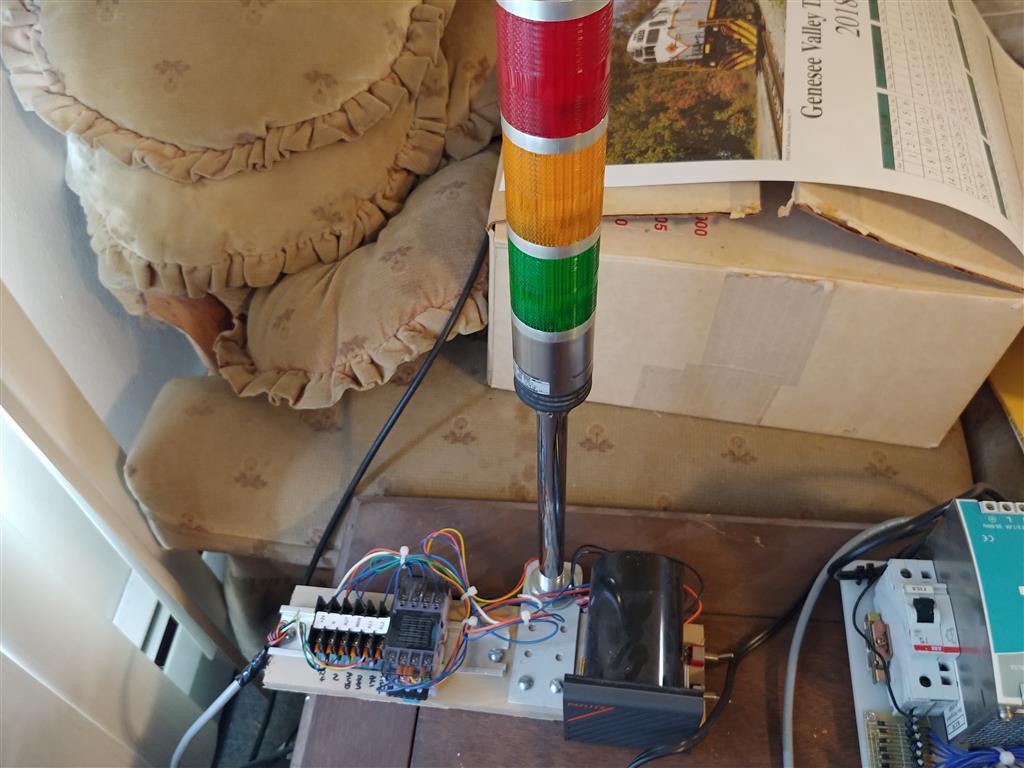
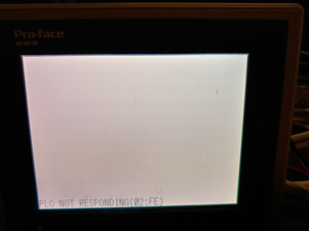
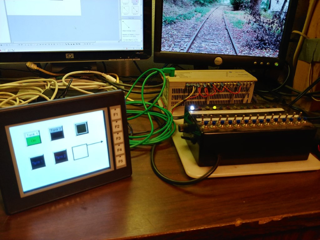
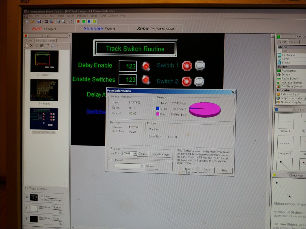
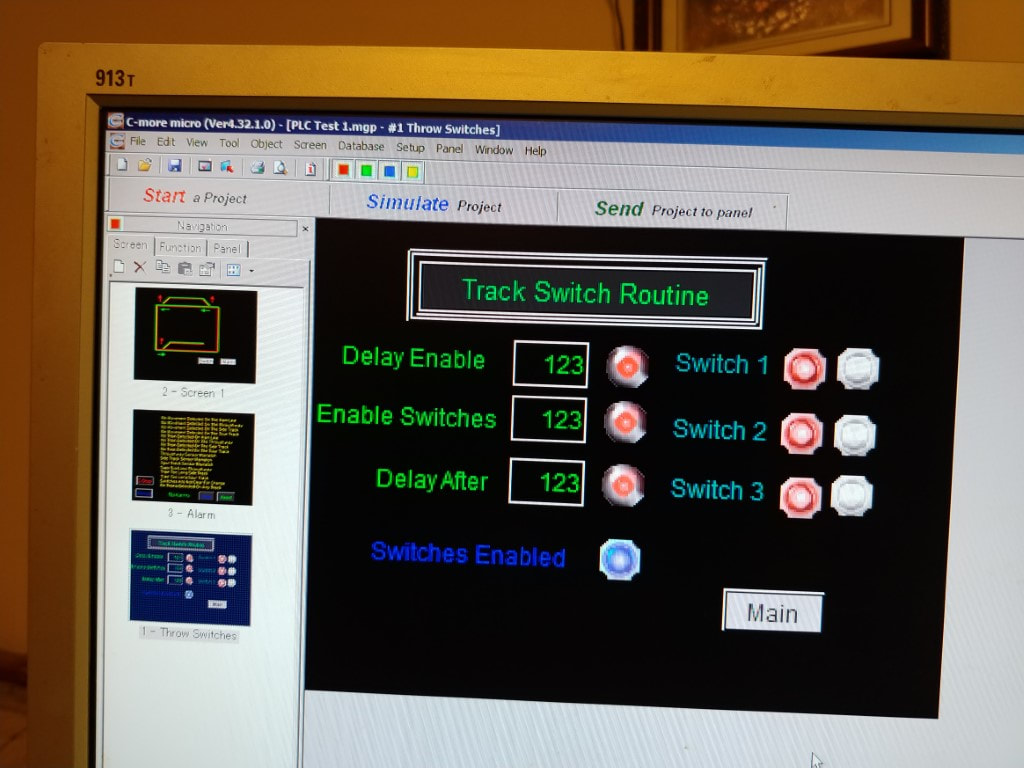
HMI panel initial test and programming
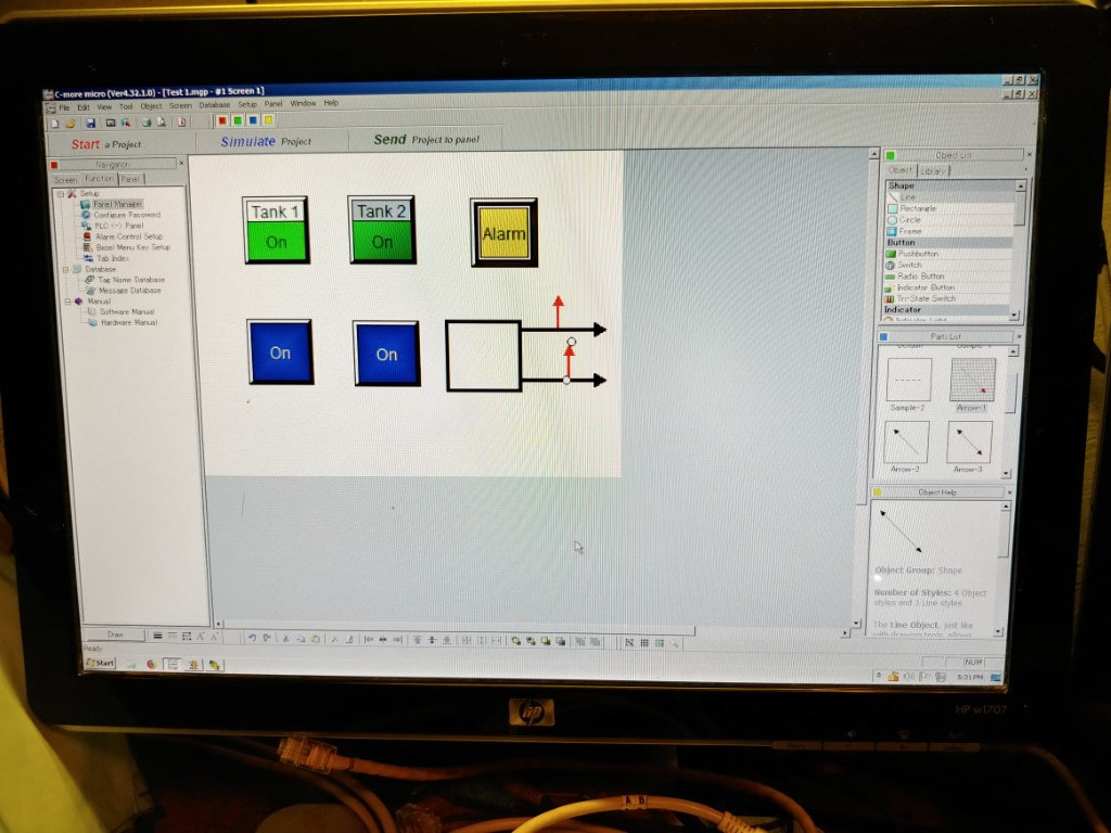

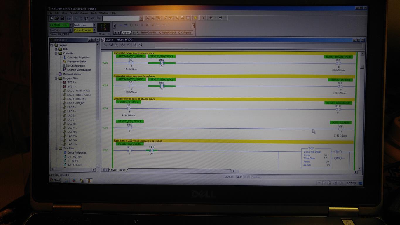
The next step was to write the "Forward - Reverse" code as a subroutine so it can operate different sections of the track. I need 4 areas controlled by this routine.
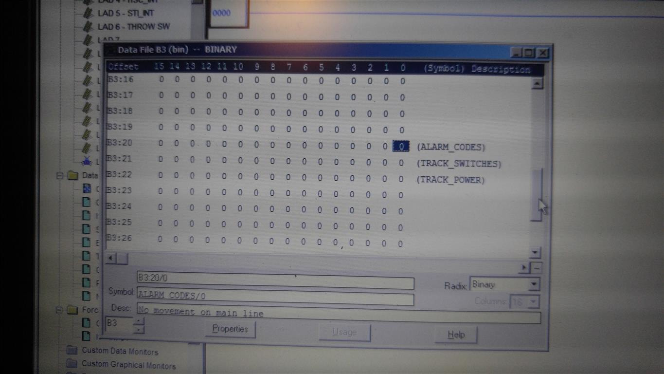
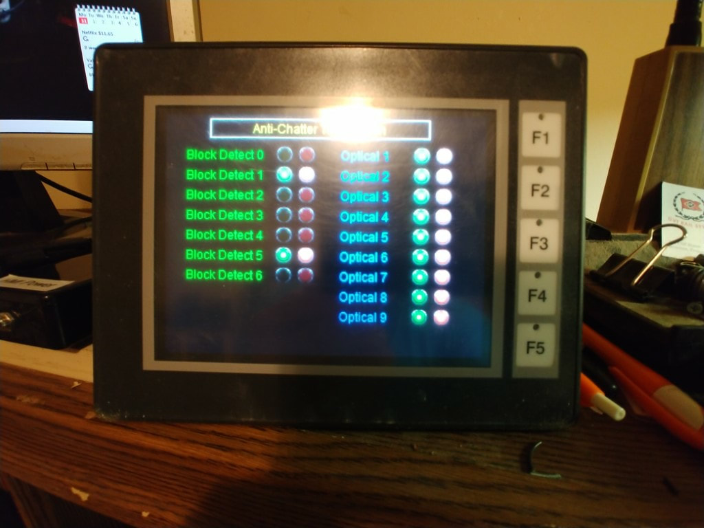
Second part showing why I have the alarm codes as bits. This will be important for the HMI panel.
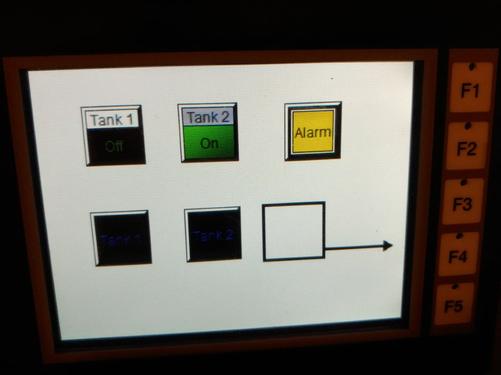
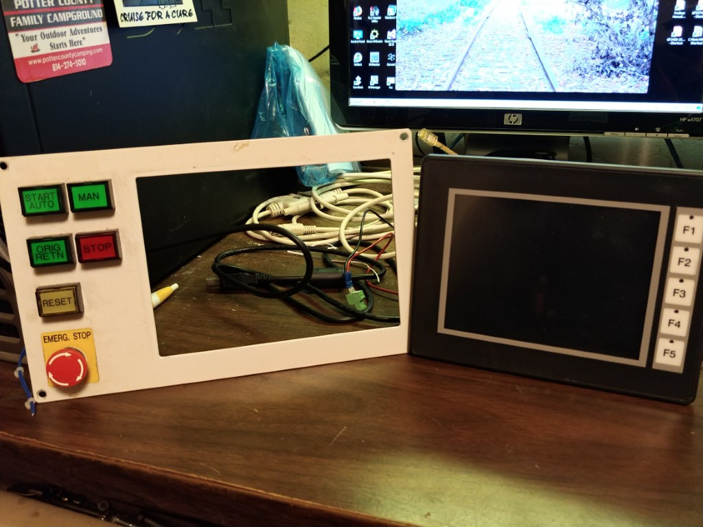
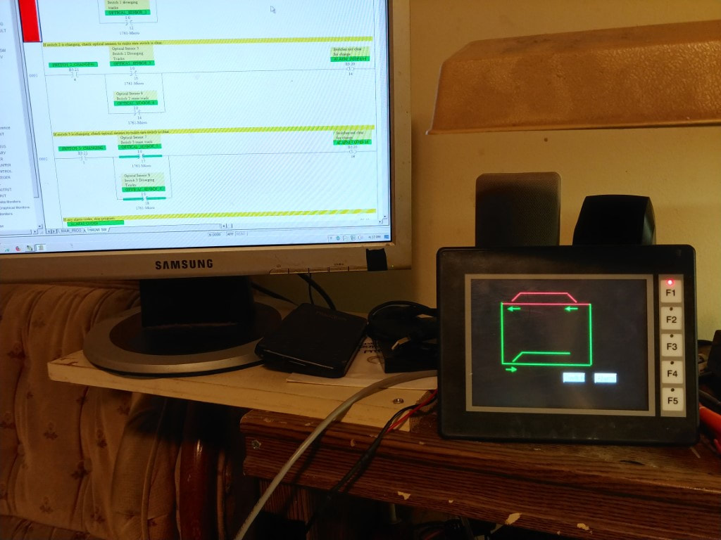
Initial tests with the HMI panel.
These were just initial tests, All I did was integrate it into an existing program, but it is also possible to have buttons on the HMI panel that can do the selections that I am doing with the buttons, and to do other routines. So far this panel is working well.
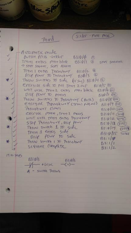
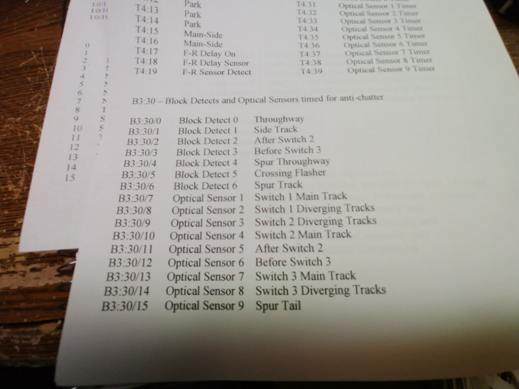
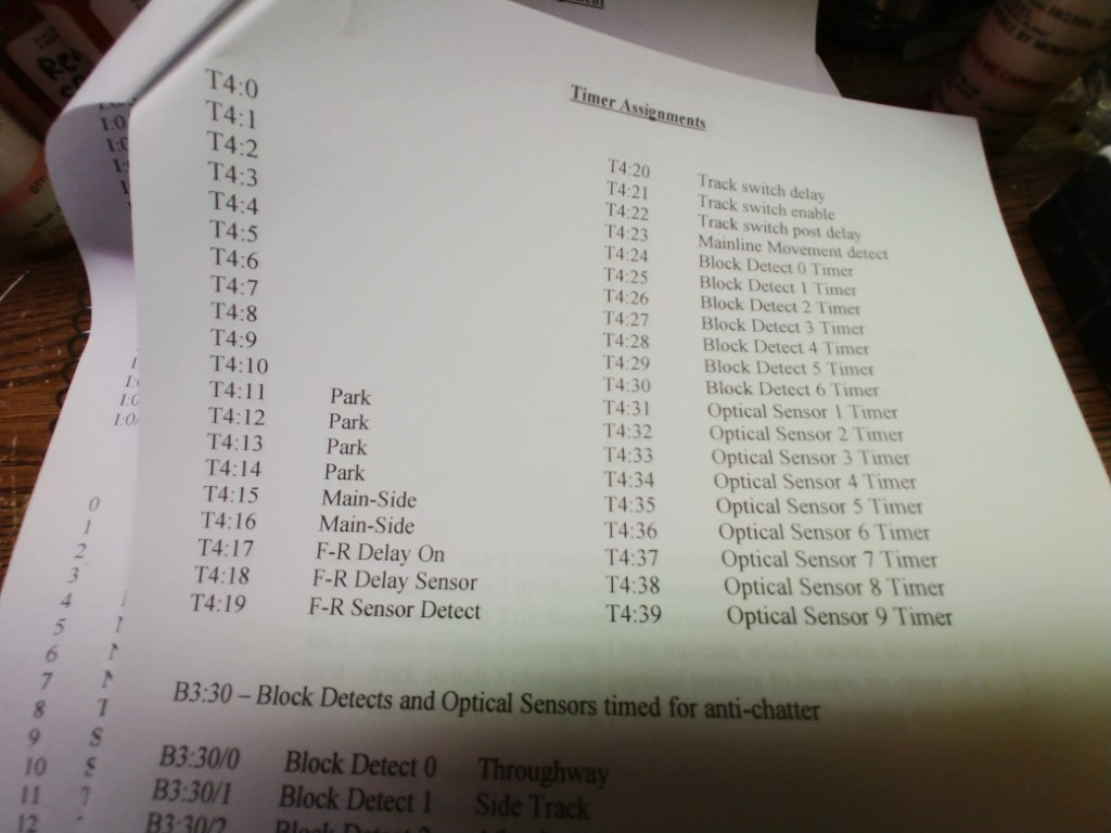
The next step is updating my notes with the data blocks used in the PLC. I have also found that even with the capacitors on the input block there is still chatter on the inputs and the optical sensors have to be set at an extreme angle to avoid seeing between the cars. This means the side track area is shorter because of this angle and causing issues. I wrote in a new subroutine to hopefully deal with this situation which I am calling an "anti-chatter" Videos showing the next routine and the chatter issue are below.


Main and Side train interchange, Version 1
This video is a first version of an endless running program that allows the main and side trains to run the track for a set number of laps. This routine also shows two issues that need to be addressed, one is the chatter on the input blocks, the other is when track power is shut down, some trains will coast too far causing it to block the sensors.
Concept program to park the train on a block.
Input block chatter and subroutine test
This video demonstrates the electrical noise and chatter that is seen on the input blocks. Part of the issue is the optical sensors that sometimes can see between the cars as the train passes through. The second issue is as the train enters and exits a block detect track section, The leading or trailing wheels can sometimes cause a double bounce in the detection routine. I wrote in a subroutine using timers to adjust for this situation and will allow fine tuning the timers for the best results. It will also allow the optical sensors not to be at such a steep angle to the track as it can ignore the gaps between the cars.