CW80 Transformer and Crossing Flasher circuit
When I
discovered that the crossing flasher would not work out of the box. I
designed a circuit to make it flash using the accessory activator pack. I
knew the output was AC voltage so I designed a basic full wave bridge
to convert it to DC and used a 7805 voltage regulator to power the
circuit. It looked good on paper but every time I ran the train the
regulator would overheat and burn up. After several attempts I did some
searching on the internet and came across this video about this
transformer.
As this video
shows, the track power is not an AC sine wave with a varying amplitude
as you would think it would be. The way to overcome this is to increase
the filter capacitor to a much larger value.
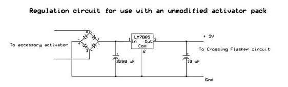
This circuit
was used to provide the power for the crossing flasher. The next step
was to make the flasher. I wanted a nice clean on & off flash so I
used a logic chip diagram that is commonly found.
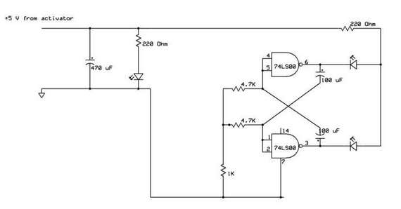
In this diagram
I used a 74LS00N chip rather then the 7400N only because it is what I
had on hand. The only difference is the capacitors that control the
flash rate would need to be increased for a 7400N chip. I added a small
LED on the control box to indicate when the circuit is activated.
This short
video shows it operating. In this video I used the accessory activator
pack to power the flasher. Later on I removed the regulation circuit and
now have it powered from a separate source. This way if a train is
stopped on the block, the flasher will still work.
Lionel Remote Switches
This is an O72
Left hand switch for my spur line. You can see three sets of wires
coming from the switch. The first is the black cable which leads to the
remote switch controller as it comes from Lionel. The second nearly
clear wires are the power source for the switch. Normally the switches
use track power but with a small change they can be operated off a
separate power source. The third set (brown/white) are ties to the "RSC
Lights" to sense switch position for my signal system. The other wires
pass under to the signal and are not connected to the switch
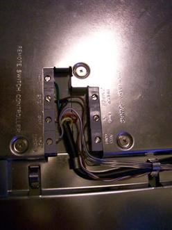 |
Underside view of the switch. The terminals are labeled as follows. Starting left
Thru Gnd Out RSC Lights The right side terminals Track Jumper AUX In AUX Gnd Normally there is a jumper connecting "Track Jumper" to "AUX In" which means the switch uses track power. Pulling out the jumper allows you to power the switch from another source. |
The way the
controller works is by using two momentary contact pushbuttons. by
touching either THRU or OUT (for turnout) to the GND terminal will throw
the switch to that position. Thats also turns the signal lamp 90
degrees to show either blue or red on the switch. On the remote switch
it will either glow green for THRU selected or red for OUT selected. The
signal for this is called "RSC Lights" The way this works is if the
THRU is selected, RSC Lights has +4.5 volts on it. If the OUT is
selected, RSC lights has -4.5 volts on it. So the lighting in the remote
switch is nothing more then a green and red LED wired back to back. So
that can provide a way to sense the switch position.
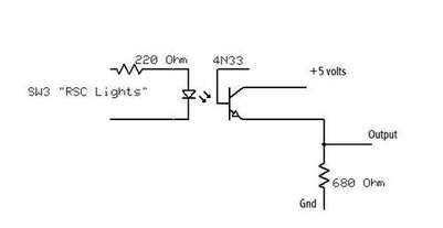
The 4N33 is
actually a Darlington transistor but the schematic only shows it as one.
The 220 Ohm resistor is connected to RSC Lights. and the Cathode is
connected to the GND wire. This way when the switch is selected THRU and
glowing green, the isolator is active. The 680 Ohm resistor provides a
pulldown so the output doesn't float when the isolator is not active.
The output from this is suitable as an input for logic gates.
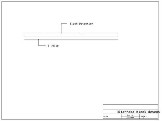
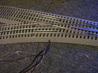
Fast Track sections and block detection
This part will
show how to use the activator packs as block detection. The way this set
normally works is you get two smaller section with one outer rail
isolated. Then the larger center section has two wires connected to the
center rail and the outer rail that is isolated by the two smaller
blocks. What happens is when a train rolls over this section, the wheels
connect the two outer rails (which are common) and the wires have track
power present as long as a train is in this block. The outer two rails
are common and the center rail is the hot wire. The 3-rail design allows
you to have reversing loops or a "wye" without worry about short
circuits.
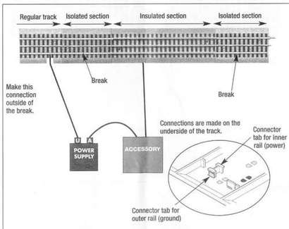
Since my signals are designed using logic circuits, What I did was feed 5 volts to the outer rail and then the blocks will show a 5 volt output when a train occupies the block. The power source for this must be separate from the train power since I am connecting it to the ground side of the track power.