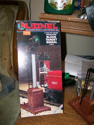
Signal Modification

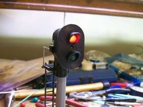
Signal Circuits
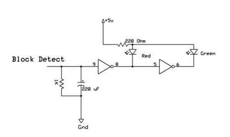
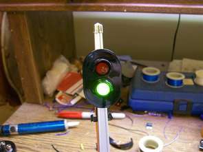
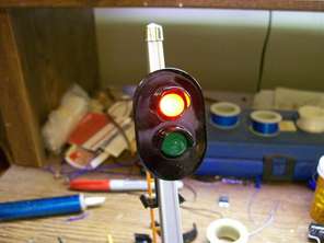
This is a basic
block circuit which can be used with a modified block signal. There is
need for some filtering of the input voltage from the block detector
since it will be "noisy" from the wheels running on the track. There is
also a pull down resistor which is needed since the input for a logic
gate shouldn't float (no connection) This circuit would light the green
LED when there is no train present and trip the red LED when a train is
in its block. This circuit would act much like the way the Lionel block
signal would operate with the pressure pad under the track.
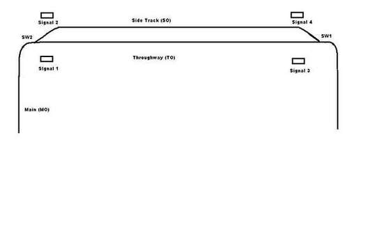
This diagram
shows the placement of the four signals and the two switches. This side
track will allow parking one train while another one runs the track. By
using an isolated block (the switches do come with one) you can control
the track power on the side. The block detection does not depend on
track power so even a train sitting on the side track with no power will
be seen by the block detector. The train runs right to left.
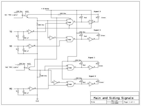
This circuit
senses the switch positions and if the blocks are occupied. A green
(clear) condition would be present only if the block ahead is clear and
the switch is thrown in the correct position. The circuit utilizes
optoisolators for the switches and filtering of the input from the block
detectors.
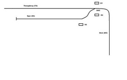
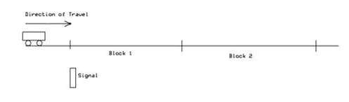
This is a
diagram of the spur line. I placed the spur on the inside of the loop so
when the layout is wall mounted it will allow me to change trains on
the spur while the layout is running. I used two dwarf signals in the
same way the signals 3 and 4 are shown in the prior diagram. I will
explain "D3" below.
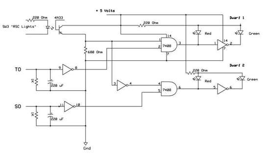
The diagram for the two dwarf signals is the same as the signals 3 and 4 of the diagram shown above.
Since the spur line would require a train to back out to the main. I thought adding a signal facing the spur line would add a nice effect. What I thought would be better then a red & green signal was to make the green LED blink to indicate the train is clear to back out but at a reduced speed. The circuit works that it must see the switch is thrown to the spur line and that there is a train in the spur to back out. This also means the dwarf signal would show a stop condition since the spur is already occupied. I also used a higher signal so the train would see it but the head looks just like the dwarf signals.
Since the spur line would require a train to back out to the main. I thought adding a signal facing the spur line would add a nice effect. What I thought would be better then a red & green signal was to make the green LED blink to indicate the train is clear to back out but at a reduced speed. The circuit works that it must see the switch is thrown to the spur line and that there is a train in the spur to back out. This also means the dwarf signal would show a stop condition since the spur is already occupied. I also used a higher signal so the train would see it but the head looks just like the dwarf signals.
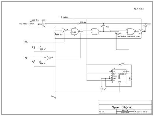
The spur signal
incorporates a 555 timer circuit as an input to the AND gate that
controls the green LED. That provides the blinking when the green LED is
turned on. I also added a small switch to disable the blinking if
desired. It would then just show a solid green.
Since the spur
signal is also designed to detect if a train is blocking its path on the
main. I needed to add another block detector closer to the switch.
This way if a train is coming around the main the signal will trip a
stop condition to avoid a collision. That also means that section of
track has two block detectors and opens the possibility of installing a 3
aspect signal so each side of the room will have a signal for a more
balanced look
This diagram illustrates a 3 aspect signal with two block detectors.
A three aspect signal will have a green, yellow, and red light. when the blocks are not occupied, the signal shows green "clear" which means a train and proceed at normal speed. Once a train passes into the first block the signal will trip red "stop" so a train approaching would have to stop. Once the train enters the second block and is clear of the first block the signal will change to yellow "approach". This means a train coming in next can proceed but at a reduced speed since there is another train ahead of it. Once the train has exited both blocks will the signal revert back to green "Clear"
A three aspect signal will have a green, yellow, and red light. when the blocks are not occupied, the signal shows green "clear" which means a train and proceed at normal speed. Once a train passes into the first block the signal will trip red "stop" so a train approaching would have to stop. Once the train enters the second block and is clear of the first block the signal will change to yellow "approach". This means a train coming in next can proceed but at a reduced speed since there is another train ahead of it. Once the train has exited both blocks will the signal revert back to green "Clear"
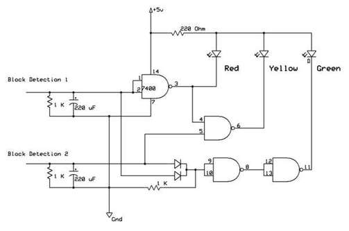
This circuit
uses only 1 logic clip and could be possibly integrated right into the
signal. The two diodes act as an "OR" gate for the green light. This way
if either block is occupied, the green light must be off. The red light
would come on if block 1 is occupied. The yellow light only comes on if
block 1 is open and block 2 is occupied. In a sense this is actually
three circuits integrated into one. I have built a prototype of this
circuit to test it but I am looking for a 3 aspect signal to use.